11. SATA 2 connector (black)
12. M.2 WLAN connector
13. SATA0 connector (blue)
14. PCIe x16 (Slot2)
15. PCIe x4 (Slot4)
16. PCIe x1 (Slot1/2)
17. PCIe x1 (Slot1/2)
18. M.2 PCIe SSD connector
19. Type-C connector
20. Processor socket
21. Keyboard and Mouse serial connector
22. Video connector
23. Intrusion switch connector
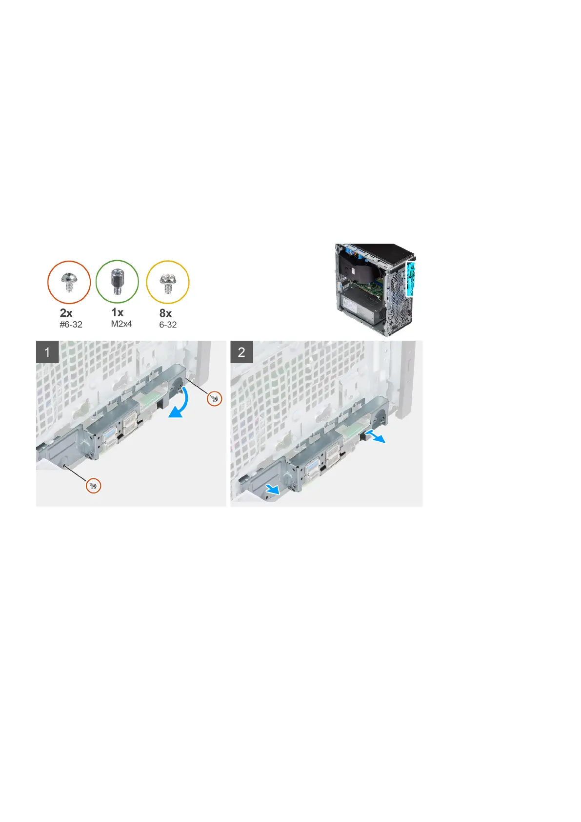
The following images indicate the location of the system board and provide a visual representation of the removal procedure.
Removing and installing components 75