b memory module
c heat sink assembly
d SD card
e M.2 PCIe SSD
f processor
g cooling shroud
h optical drive
i 2.5 inch hard drive assembly
j front bezel
k cover
8 Follow the procedure in After working inside your computer.
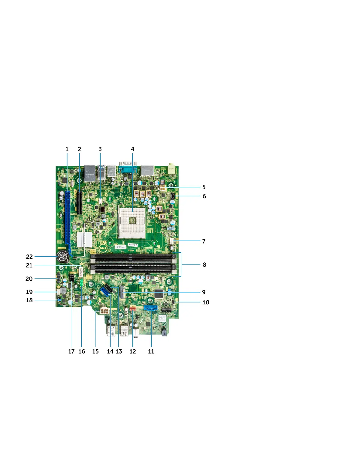
System board layout
This chapter explains about the motherboard's layout with name and location of its connectors.
1 PCI-e x16 Connector (SLOT2) 2 PCI-e x4 Connector (SLOT1) - open ended X4 to support
X16
3 VGA Daughter Board Connector (VGA) 4 Processor Socket (CPU)
5 CPU Power Connector (ATX_CPU) 6 Intrusion Switch Connector (INTRUDER)
7 CPU fan Connector (FAN_CPU) 8 Memory Slots (DIMM1,DIMM2,DIMM3,DIMM4)
9 M.2 Slot 3 Connector (M.2_SSD) 10 Power Switch Connector (PWR_SW)
11 Media Card Reader Connector (CARD_READER) 12 System fan Connector (FAN_SYS)
Disassembly and reassembly 41