Installing System Components 165
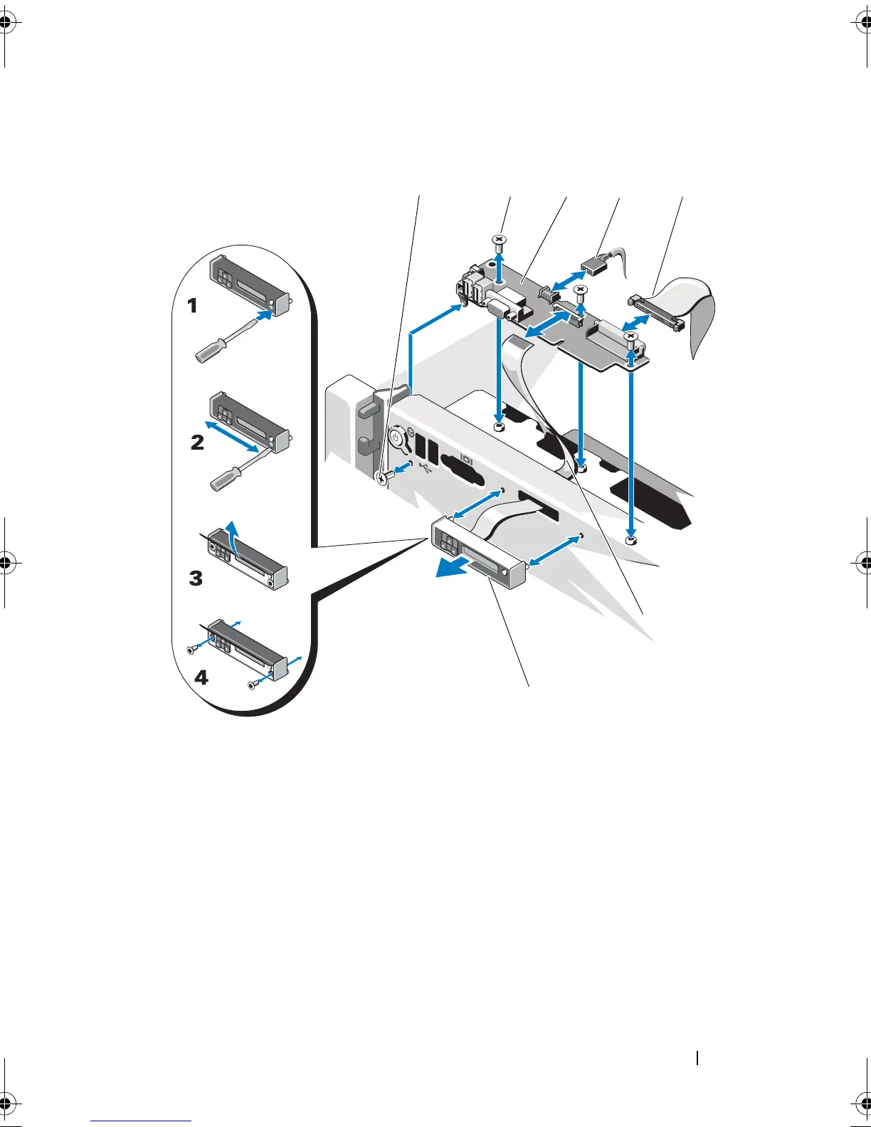
Figure 3-36. Removing or Installing the Control Panel Assembly
1 T8 Torx screw 2 T10 Torx screws (3)
3 control panel board 4 USB cable
5 control panel cable 6 display module cable
7 display module
book.book Page 165 Wednesday, January 20, 2010 10:20 AM