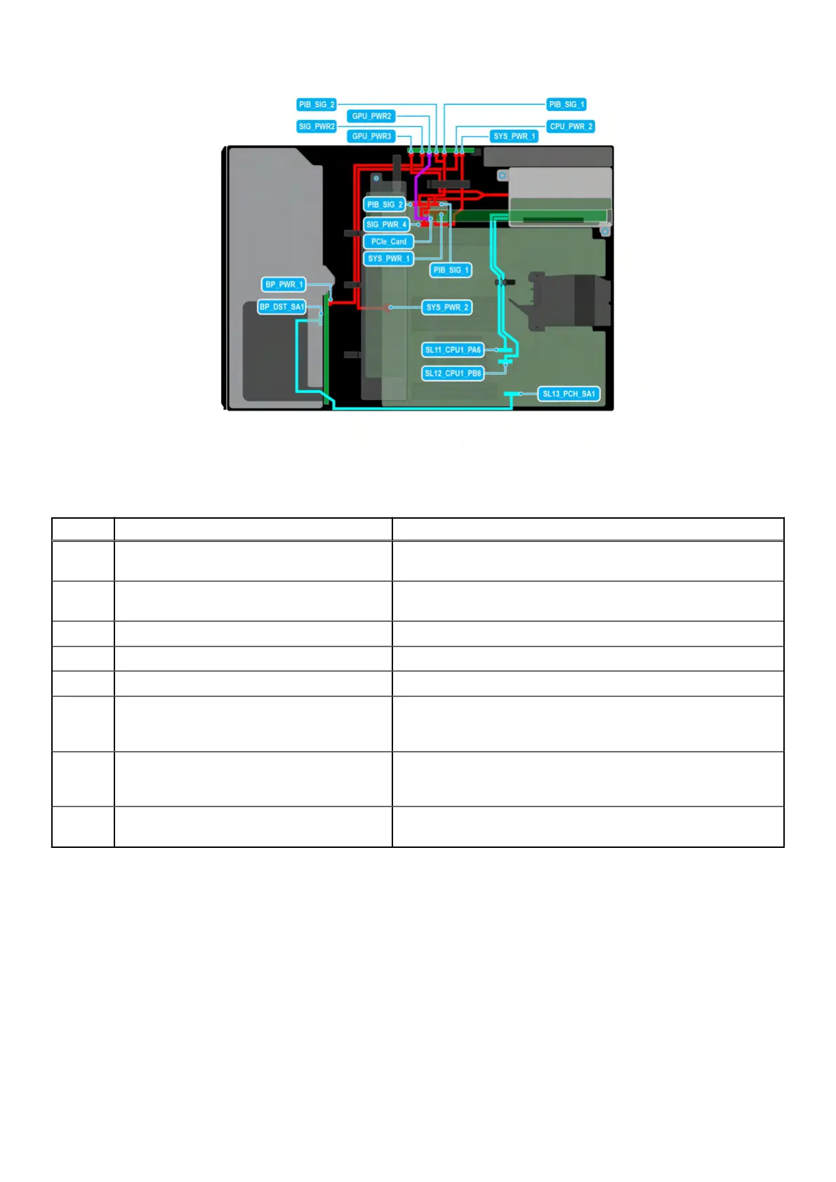
Figure 42. Configuration 4: 8 x 3.5-inch (Chipset SATA) + 1 x GPU on CPU 1
Table 74. Configuration 4: 8 x 3.5-inch (Chipset SATA) + 1 x GPU on CPU 1
Order From To
1 SYS_PWR_1 (Power connector on system
bo
ard)
SYS_PWR_1 (Power connector on PIB)
2 SYS_PWR_2 (Power connector on system
board)
CPU_PWR_2 (Power connector on PIB)
3 BP_PWR_1 (Backplane power connector) SIG_PWR_2 (Power connector on PIB)
4 BP_DST_SA1 (Signal connector on backplane) SL13_PCH_SA1 (Signal connector on system board)
5 PCIe card GPU_PWR1 and GPU_PWR2 (GPU power connectors on PIB)
6 PIB_SIG_1 (PIB signal connector on system
board) and PIB_SIG_2 (PIB signal connector
on system board)
PIB_SIG_1 (PIB signal connectors on PIB) and PIB_SIG_2 (PIB
signal connectors on PIB)
7 SIG_PWR_4 (Power connector on system
board) and GPU_PWR3 (GPU power
connector on PIB)
RISER_PWR_1 (GPU Riser)
9 SL11_CPU1_PA6 and SL12_CPU1_PB6 (Signal
connectors on system board)
GPU Riser 2
Installing and removing system components 97