EasyManua.ls Logo

Dell PowerEdge T710 - Page 130

Dell PowerEdge T710
214 pages
To Next Page IconTo Next Page
To Previous Page IconTo Previous Page
Loading...
130 Installing System Components
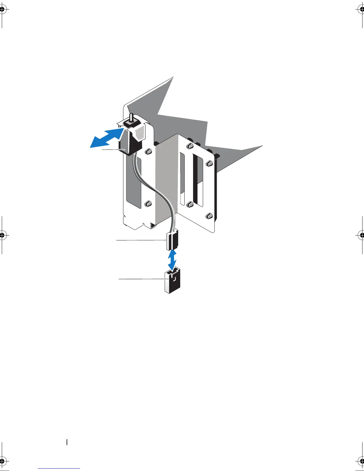
Figure 3-22. Removing and Installing the Chassis Intrusion Switch
1 chassis intrusion switch 2 chassis intrusion switch cable
3 intrusion connector on the system
board
1
2
3
book.book Page 130 Monday, June 15, 2009 11:33 AM

Table of Contents

Other manuals for Dell PowerEdge T710

Related product manuals