Fan module installation
The fan modules in the S4100–ON Series switch are field replaceable.
When looking at your switch, Slot 1 is on the left side of the switch and Slot 4 is on the right side of the switch.
CAUTION: DO NOT mix airflow directions. All fans must use the same airflow direction—reverse or normal. If
you mix the airflow direction, to avoid overheating the switch, correct the mixed airflow.
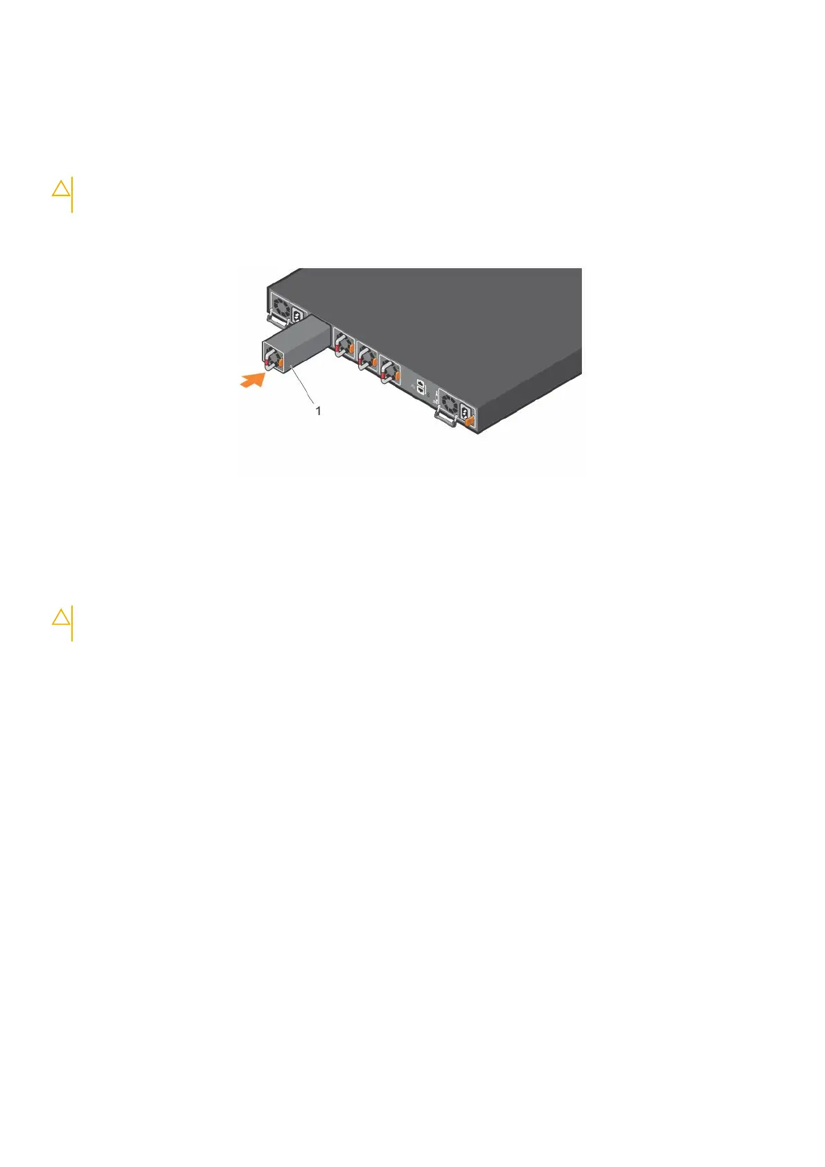
1. Take the fan module out of the shipping box.
2. Slide the module into the bay.
Figure 27. S4100–ON Series fan modules installation
1. Fan unit
Fan module replacement
To request a hardware replacement, see Dell support.
CAUTION:
Complete the following steps within one minute or the switch temperature could rise above safe
thresholds and the switch could shut down:
1. Slide the fan module out of the bay.
2. Slide the replacement module into the bay.
Fans
37
 Loading...