INSTALLATION SM15K
17 / 32 DELTA ELEKTRONIKA B.V. rev. January 2021
appear next to the actual current value or 'CP' will appear
next to the actual power value.
5.13.3 CC+ & CC- SETTINGS
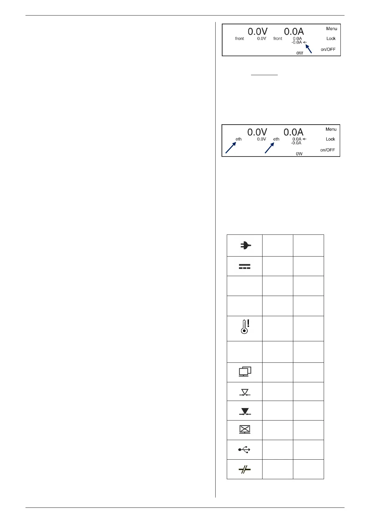
By default the A-knob at the front can be used to set the CC+.
Set the function of the A-knob via Menu > Front Settings >
Knobs: here select 'Iset-' or 'Iset+'. In the display the arrow
behind the value for the current changes position. See
fig. 5 - 18.
Select the options to enable sinking under special conditions
via Menu > Powersink > Curr- Permissions.
Here it can be set to sink during RSD, Interlock and Output
Off.
By pressing both the button 'Lock' followed by 'Menu' at the
same time, the function of the A-knob also changes from 'Iset-
' to 'Iset+'.
5.13.4 POWER+ & POWER- SETTINGS
Set the values for maximum sink and source power via
Menu > Configuration > Prg Setting > P-Settings and here
rotate the V-knob to set the source power, and the A-knob to
set the sink power.
In the default configuration, the settings for CV, CC and CP
Limit are set to the maximum values.
Set the limits via Menu > Protection > Limits.
5.13.6 REMOTE PROGRAMMING
Before the set values, the selected source is shown, see
fig. 5 - 19. For example 'eth', 'web', 'seq', 'slot1' etc.
For more information, see chapter 6 of this manual.
This indicator is active if the AC input voltage is too low / too
high, or if a phase is missing.
DC FAIL
This indicator is active if the DC power terminals are 5%
below or above the set value for the voltage.
OVER VOLTAGE
This indicator is active if the voltage on the DC power
terminals is 102.5% or more. The output will remain ON.
SELF PROTECT
This indicator is active if the voltage on the DC power
terminals is 105% or more. The output will switch to OFF.
Reset by pressing the OUTPUT ON/OFF button.
OVER TEMPERATURE
This indicator is active if the temperature measured by one of
the sensors is higher than 90°C. The output will shutdown
until the temperature has dropped below 80°C.
LIMITER
This indicator is active if one of the settings for CV, CC or CP
is limited.
LAN
This indicator is active if the unit is connected to a LAN.
INTERLOCK
This indicator is active if the terminals of the interlock
connecter have been interrupted.
COMMUNICATION WATCHDOG
This indicator is active if the communication watchdog timer
has expired**.
REMOTE SHUTDOWN
This indicator is active if the DC terminals of the unit are
shutdown via the ETH connection, or via an optional interface.
USB
Not available in firmware package P0140.
SMIN / SPLUS BREAK
Not available in firmware package P0140.
fig 5 - 18
When the arrow appears behind the negative current
settings, the sink current can be adjusted with the A-
knob at the front panel.
fig 5 - 19
The programming source appears before the
settings. In this example both CV and CC settings
are controlled via Ethernet.
 Loading...


