ADJUSTING LOWER
BLADE GUIDES AND
GUIDE BRACKET
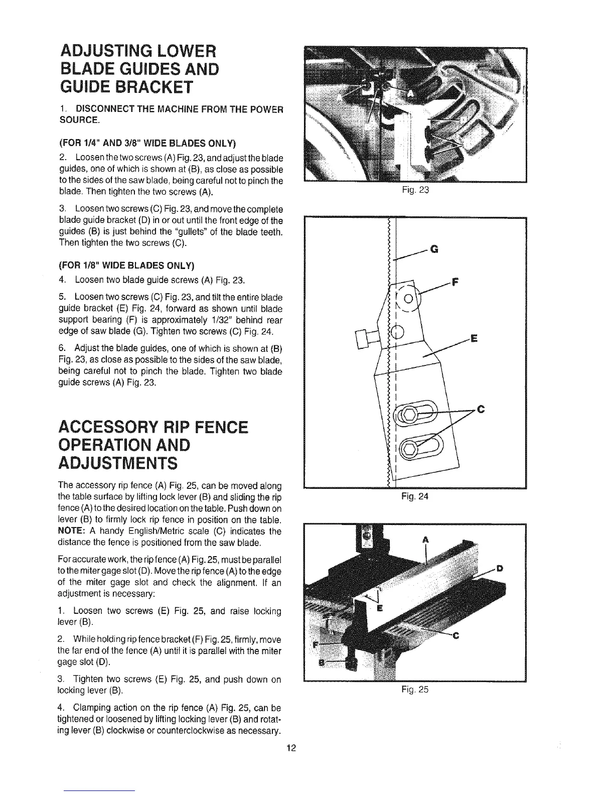
1. DISCONNECT THE MACHINE FROM THE POWER
SOURCE.
(FOR 1/4" AND 3/8" WiDE BLADES ONLY)
2. Loosen the two screws (A) Fig. 23, and adjust the blade
guides, one of which is shown at (B), as close as possible
to the sides of the saw blade, being careful not to pinch the
blade. Then tighten the two screws (A).
3. Loosen two screws (C) Fig. 23, and move the complete
blade guide bracket (D) in or out until the front edge of the
guides (B) is just behind the "gullets" of the blade teeth.
Then tighten the two screws (C).
(FOR 1/8" WiDE BLADES ONLY)
4. Loosen two blade guide screws (A) Fig. 23.
5. Loosen two screws (C) Fig. 23, and tilt the entire blade
guide bracket (E) Fig. 24, forward as shown until blade
support bearing (F) is approximately 1/32" behind rear
edge of saw blade (G). Tighten two screws (C) Fig. 24.
6. Adjust the blade guides, one of which is shown at (B)
Fig. 23, as close as possible to the sides of the saw blade,
being careful not to pinch the blade. Tighten two blade
guide screws (A) Fig. 23.
ACCESSORY RiP FENCE
OPERATION AND
ADJUSTMENTS
The accessory rip fence (A) Fig. 25, can be moved along
the table surface by liftinglock lever (B) and sliding the rip
fence (A) to the desired location on the table. Push down on
lever (B) to firmly lock rip fence in position on the table.
NOTE: A handy English/Metric scale (C) indicates the
distance the fence is positioned from the saw blade.
For accurate work, the rip fence (A) Fig. 25, must beparallel
tothe miter gage slot (D). Move the rip fence (A) to the edge
of the miter gage slot and check the alignment. If an
adjustment is necessary:
1. Loosen two screws (E) Fig. 25, and raise locking
lever (B).
2. While holding ripfence bracket (F) Fig. 25, firmly, move
the far end of the fence (A) until it is parallel with the miter
gage slot (D).
3. Tighten two screws (E) Fig. 25, and push down on
locking lever (B).
4. Clamping action on the rip fence (A) Fig. 25, can be
tightened or loosened by liftinglocking lever (B) and rotat-
ing lever (B) clockwise or counterclockwise as necessary.
12
Fig. 23
i jG
1
C
'Ul
Fig. 24
Fig. 25
 Loading...