12 13
I
a
dd
gg
H
F
E
G
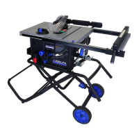
ASSEMBLY
FIGURE 4
Secure the support rod assemblies to the support rod connect tube using two M8 x 30 Carriage bolts (gg) and M8 lock
nuts. (dd)
See Figure 4 & 4a.
FIGURE 3
ASSEMBLING THE STAND
Layout the left and right support rod assemblies (E & F).
Place the cross connect assembly (H) between the support rod assemblies and connect the support rod connection tube
(G) to the ends of the support rod assembly tubes as shown in Figure 3.
NOTE: Ensure foot pads are oriented as shown in Figure 3.
FOOT
PADS