Chapter 8 ParametersASDA-A2R Series
Revision December, 2014
8-281
Setting Value: 0x0F
DI Name Function Description of Digital Input (DI)
Trigger
Method
Control
Mode
SPDKVC Switch between the 1
s
set of analog (P1-40) and the 2
n
set
(P1-81)
Level
triggered
S
Setting Value: 0x10
DI Name Function Description of Digital Input (DI)
Trigger
Method
Control
Mode
SPDLM In torque mode, when the DI is ON, the motor speed will be
limited, the limited speed command will be internal register
or analog voltage command.
Level
triggered
T
Setting Value: 0x11, 0x12, 0x13, 0x1A, 0x1B, 0x1C
DI
Name
Function Description of Digital Input (DI)
Trigger
Method
Control
Mode
POS0
POS1
POS2
POS3
POS4
POS5
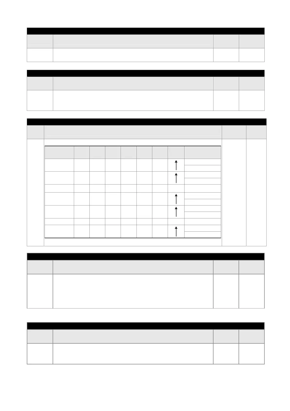
PR Command Selection (1~64)
Position
Command
POS5 POS4 POS3 POS2 POS1 POS0 CTRG
Corresponding
Parameter
Homing 0 0 0 0 0 0
P6-00
P6-01
Procedure1 0 0 0 0 0 1
P6-02
P6-03
~
Procedure
50
1 1 0 0 1 0
P6-98
P6-99
Procedure
51
1 1 0 0 1 1
P7-00
P7-01
~
Procedure
63
1 1 1 1 1 1
P7-26
P7-27
Level
triggered
PR
Setting Value: 0x1D
DI Name Function Description of Digital Input (DI)
Trigger
Method
Control
Mode
ABSE
When DI.ABSE is ON, it is in ABS mode. DI.ABSQ, DI.ABSC,
DI.ABSR, DI.ABSD and DI.ABSC are enabled.
When DI.ABSE is ON, the function of DI4, DO2, DO3 will be
disabled. Function of DI4 will be ASDQ, DO2 will be ABSR
and DO3 will be ABSD.
Level
triggered
ALL
Setting Value
Setting Value: 0x1F
DI Name Function Description of Digital Input (DI)
Trigger
Method
Control
Mode
ABSC
When DI.ABSC is ON, multi-turn data stored in absolute
encoder will be cleared. When DI.ABSE is ON, this function
is enabled.
Rising
edge
triggered
ALL
 Loading...
