Chapter 2 InstallationCFP2000
2-3
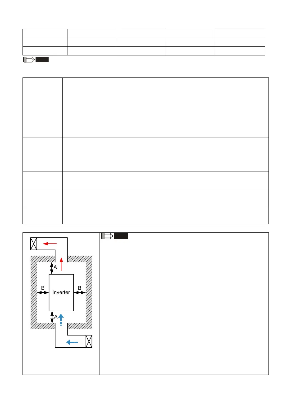
Minimum mounting clearance
Frame A [mm] B [mm] C [mm] D [mm]
A–B
60 15 -
-
C–D
100 25 -
-
NOTE
The minimum mounting clearances A–D stated in the table above applies to AC motor drives installation. Failing to
follow the minimum mounting clearances may cause the fan to malfunction and heat dissipation problems.
Frame A
VFD007FP4EA-41, VFD007FP4EA-52, VFD007FP4EA-52S,
VFD015FP4EA-41, VFD015FP4EA-52, VFD015FP4EA-52S,
VFD022FP4EA-41,VFD022FP4EA-52, VFD022FP4EA-52S,
VFD037FP4EA-41,VFD037FP4EA-52, VFD037FP4EA-52S,
VFD040FP4EA-41,VFD040FP4EA-52, VFD040FP4EA-52S,
VFD055FP4EA-41,VFD055FP4EA-52, VFD055FP4EA-52S,
VFD075FP4EA-41, VFD075FP4EA-52, VFD075FP4EA-52S
Frame B
VFD110FP4EA-41,VFD110FP4EA-52, VFD110FP4EA-52S,
VFD150FP4EA-41,VFD150FP4EA-52, VFD150FP4EA-52S,
VFD185FP4EA-41,VFD185FP4EA-52, VFD185FP4EA-52S,
VFD220FP4EA-41, VFD220FP4EA-52, VFD220FP4EA-52S
Frame C
VFD300FP4EA-41, VFD300FP4EA-52, VFD300FP4EA-52S,
VFD370FP4EA-41,VFD370FP4EA-52, VFD370FP4EA-52S
Frame D0
VFD450FP4EA-41,VFD450FP4EA-52, VFD450FP4EA-52S,
VFD550FP4EA-41,VFD550FP4EA-52, VFD550FP4EA-52S
Frame D
VFD750FP4EA-41,VFD750FP4EA-52, VFD750FP4EA-52S,
VFD900FP4EA-41,VFD900FP4EA-52, VFD900FP4EA-52S
Table 2-2
Figure 2-4
NOTE
※ The mounting clearance stated in the figure is for installing the drive in an
open area. To install the drive in a confined space (such as cabinet o
r
electri
c box), please follow the following rules: (1) Keep the minimum
mounting clearances. (2) Install a ventilation equipment or an
air
con
ditioner to keep surrounding temperature lower than operatio
n
temperature. (3) Refer to parameter setting and set up Pr.00-16, Pr.00-17
and Pr
.06-55
.
※ The table below shows the heat dissipation and the required air volume
whe
n installing a single drive in a confined space. When installing
multiple
drives,
the required air volume shall be multiplied by the number t
he
drives.
※ Refer to the table below (Airflow Rate for Cooling) for ventilation
equipment design and sele
ction.
※ Refer to the table below (Power Dissipation for AC Motor Drive) for air
conditioner design and sele
ction.
※ Different control mode affects the derating. See Pr.06-55 for more
information.
※ Refer to Section 9-4 for ambient temperature derating curve and derating
curve
s under different control mode.
Table 2-1