Chapter 2 InstallationCFP2000
2-4
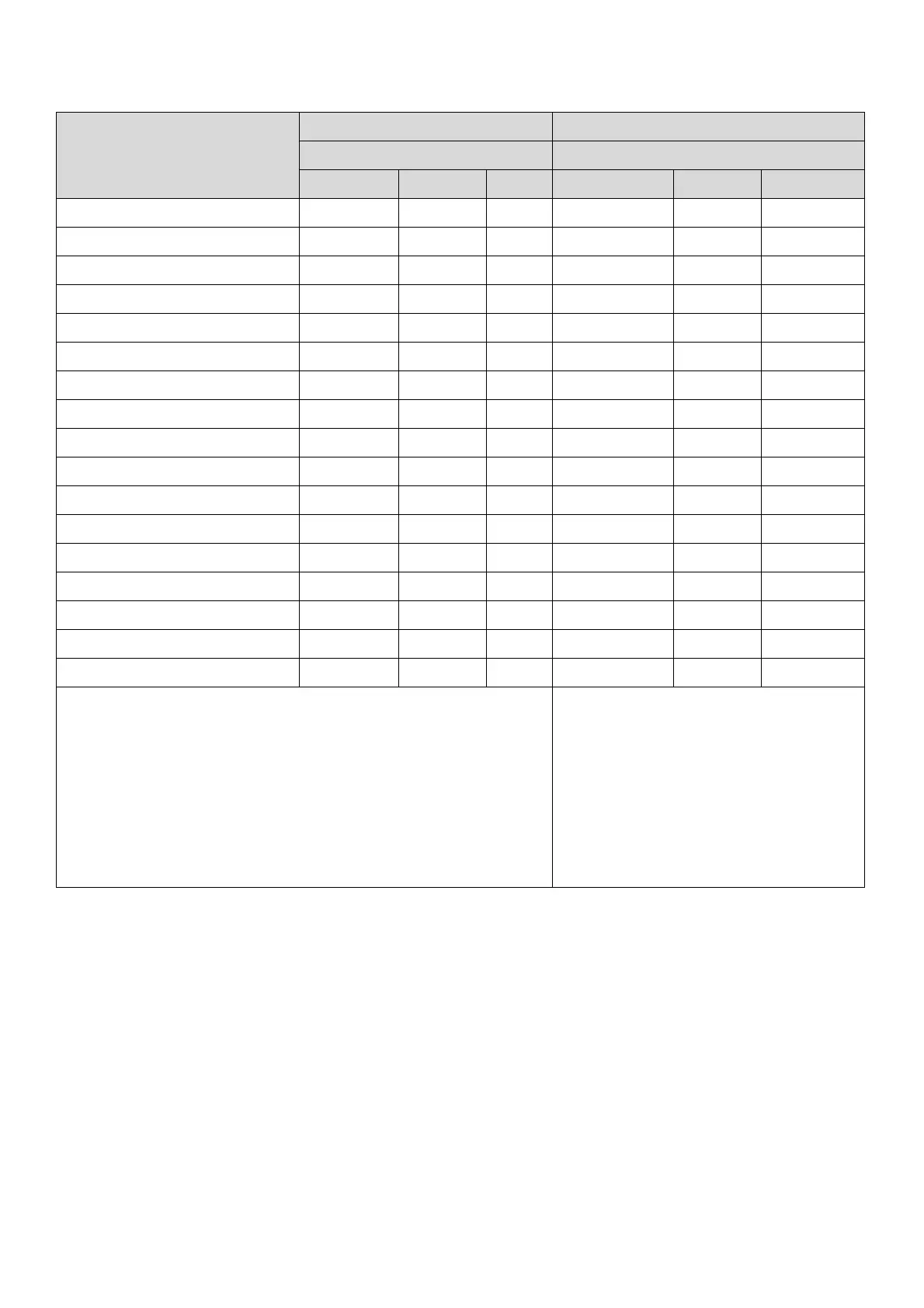
2-2 Airflow and Power Dissipation
Model No.
Airflow Rate for Cooling Power Dissipation for AC Motor Drive
Flow Rate [cfm] Power Dissipation [watt]
External Internal Total Loss External Internal Total
VFD007FP4EA-41/ 52 / 52S - 14 14 32 20 52
VFD015FP4EA-41/ 52 / 52S - 14 14 43 21 64
VFD022FP4EA-41/ 52 / 52S 34 14 48 74 25 99
VFD037FP4EA-41/ 52 / 52S 34 14 48 92 26 118
VFD040FP4EA-41/ 52 / 52S 34 14 48 113 26 139
VFD055FP4EA-41/ 52 / 52S 34 14 48 139 27 166
VFD075FP4EA-41/ 52 / 52S 34 14 48 195 29 224
VFD110FP4EA-41/ 52 / 52S 88 14 102 240 34 274
VFD150FP4EA-41/ 52 / 52S 88 14 102 309 38 347
VFD185FP4EA-41/ 52 / 52S 88 14 102 353 39 392
VFD220FP4EA-41/ 52 / 52S 88 14 102 449 47 496
VFD300FP4EA-41/ 52 / 52S 200 29 229 618 84 702
VFD370FP4EA-41/ 52 / 52S 200 29 229 726 87 813
VFD450FP4EA-41/ 52 / 52S 285 29 314 864 82 946
VFD550FP4EA-41/ 52 / 52S 285 29 314 1068 84 1152
VFD750FP4EA-41/ 52 / 52S 330 29 359 1407 111 1518
VFD900FP4EA-41/ 52 / 52S 330 29 359 1623 114 1737
※ The required airflow shown in the table is for installing single drive
in a confin
ed sp
ace.
※ When installing multiple drives, the required air volume should be
the requi
red air volume for single drive X the number of the drives.
※ The heat dissipation shown in the table
is for inst
alling singl
e drive in a confined
space.
※ When installing multiple drives, volume
of heat dissip
ation should
be the heat
dissip
ated for single dr
ive X the number
of the drives.
※ Heat dissipation for each model is
cal
culated by rated voltage, current and
default carrier
.
Table 2-3