Chapter 6 Control TerminalsCFP2000
6-9
Terminals Terminal Function Factory Setting (NPN mode)
AVI2
Auxiliary analog voltage input
Figure 6-21
Impedance: 20 kΩ
Range: 0–10 V
DC
= 0–Max. Output Frequency (Pr.01-00)
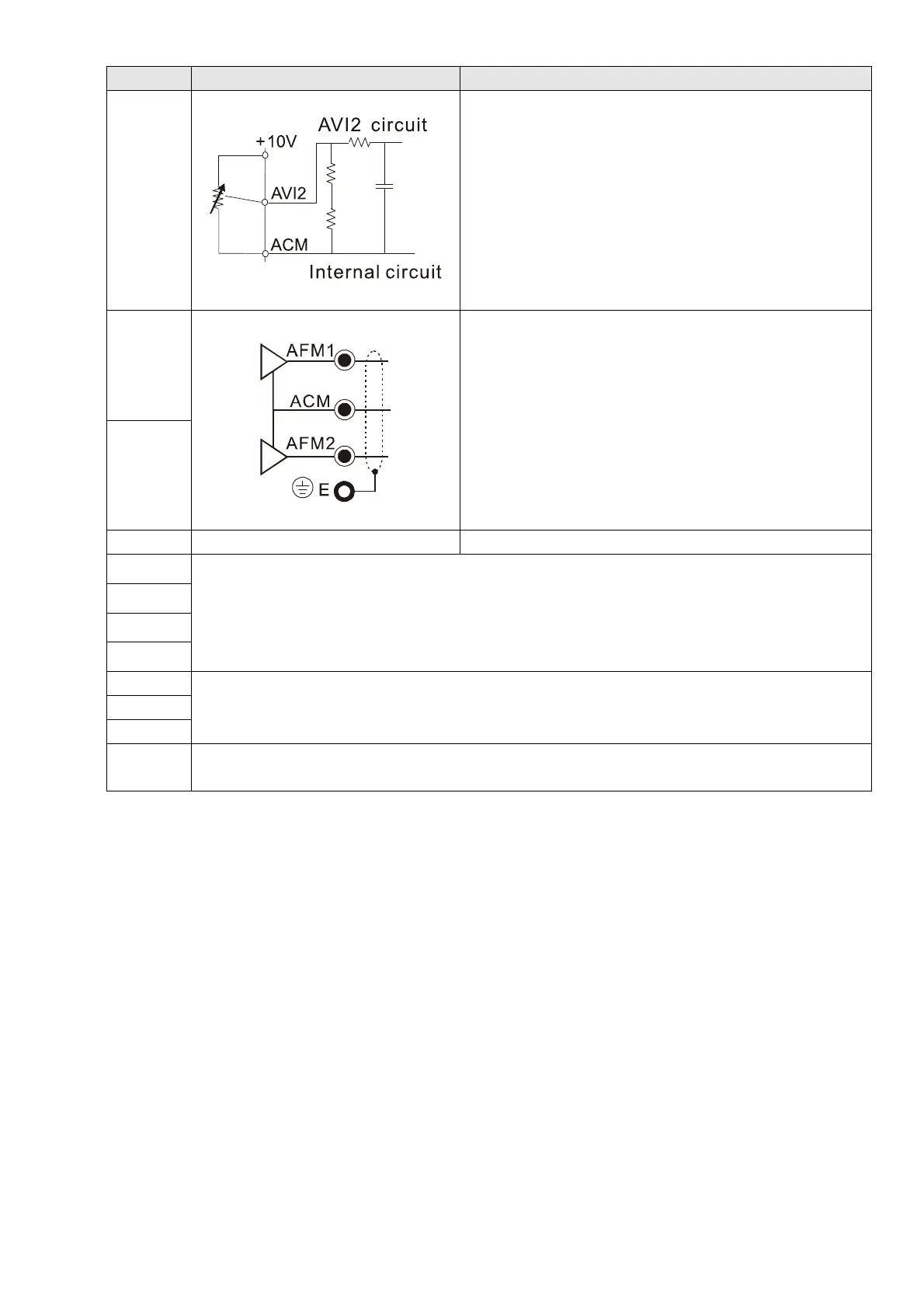
AFM1
Multi-function analog voltage output
Figure 6-22
0–10 V Max. output current 2 mA, Max. load 5 kΩ
0–20 mA Max. load 500 Ω
Output current: 20 mA max.
Resolution: 0–10 V corresponds to Max. operation
frequency
Range: 0–10 V
4–20 mA
AFM1 / AFM2 Switch, default is 0–10 V
AFM2
ACM Analog Signal Common Common for analog terminals
STO1
Default setting is shorted
Power removal safety function for EN ISO 13849 and IEC 61508
When STO1–SCM1; STO2–SCM2 is activated, the voltage of STO1–SCM1 / STO2–SCM2 must
be ≥ 11 V
DC
, the internal resistance for STO1–SCM1 / STO2–SCM2 is 3.6 kΩ
Note: Please refer to Section 18 Safe Torque Off Function.
SCM1
STO2
SCM2
SG+
Modbus RS-485
Note: Please refer to Section 12 DESCRIPTION OF PARAMETER SETTINGS group 09
Communication Parameters for more information.
SG-
SGND
RJ45
PIN 1, 2, 7, 8 : Reserved PIN 3, 6: SGND
PIN 4: SG- PIN 5: SG+
NOTE: Wire size of analog control signals: 0.75 mm
2
[18 AWG] with shielded wire.
Table 6-2
 Loading...