Chapter 12 Description of Parameter SettingsCP2000
12.1-02-14
Settings Functions Descriptions
51
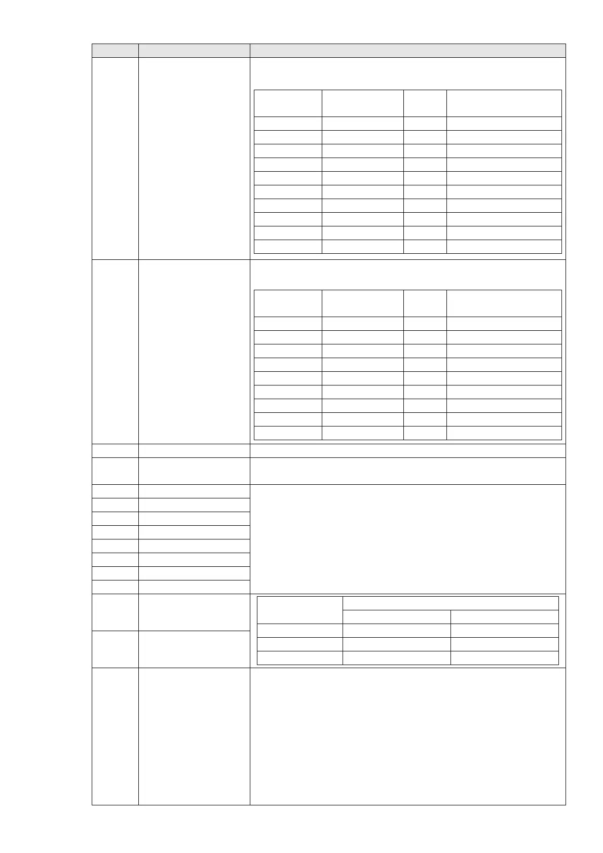
Analog output control
for RS-485 interface
For RS-485 interface (InnerCOM / Modbus) communication control
output.
Physical
terminal
Setting of related
parameters
Attribute Corresponding Index
RY1 Pr.02-13 = 51 RW The bit0 at 2640h
RY2 Pr.02-14 = 51 RW The bit1 at 2640h
MO1 Pr.02-16 = 51 RW The bit3 at 2640h
MO2 Pr.02-17 = 51 RW The bit 4 at 2640h
MO10/RA10 Pr.02-36 = 51 RW The bit5 at 2640h
MO11/RA11 Pr.02-37 = 51 RW The bit6 at 2640h
RY12 Pr.02-38 = 51 RW The bit7 at 2640h
RY13 Pr.02-39 = 51 RW The bit8 at 2640h
RY14 Pr.02-40 = 51 RW The bit9 at 2640h
RY15 Pr.02-41 = 51 RW The bit10 at 2640h
52
Output control for
communication cards
Control the output through communication cards (CMC-EIP01,
CMC-PN01 and CMC-DN01)
Physical
terminal
Setting of related
parameters
Attribute Corresponding Index
RY1 Pr.02-13 = 52 RW The bit0 at 2640
RY2 Pr.02-14 = 52 RW The bit1 at 2640
RY3 Pr.02-15 = 52 RW The bit2 at 2640
MO10/RY10 Pr.02-36 = 52 RW The bit5 at 2640
MO11/RY11 Pr.02-37 = 52 RW The bit6 at 2640
RY12 Pr.02-38 = 52 RW The bit7 at 2640
RY13 Pr.02-39 = 52 RW The bit8 at 2640
RY14 Pr.02-40 = 52 RW The bit9 at 2640
RY15 Pr.02-41 = 52 RW The bit10 at 2640
53 Fire mode indication This function is enabled when setting 58 or 59 is enabled.
54
Bypass fire mode
indication
The contact works when bypass function is enabled in the fire mode.
55 Motor 1 output
When setting multi-motor circulative function, the multi-function output
terminal automatically sets up Pr.02-13–Pr.02-15 and Pr.02-36 –
Pr.02-40 in accordance with the setting for Pr.12-01.
56 Motor 2 output
57 Motor 3 output
58 Motor 4 output
59 Motor 5 output
60 Motor 6 output
61 Motor 7 output
62 Motor 8 output
66 SO output logic A (N.O.)
Status of drive
Status of safety output
N.O. (MOx=66) N.C. (MOx=68)
Normal Broken circuit (Open) Short circuit (Close)
STO Short circuit (Close) Broken circuit (Open)
STL1–STL3 Short circuit (Close) Broken circuit (Open)
68 SO output logic B (N.C.)
67
Analog input level
reached
The multi-function output terminals operate when the analog input
level is between the high level and the low level.
Pr.03-44: Select one of the analog signal channels (
VI1, ACI, and
AVI2) to be compared.
Pr.03-45: The high level for the analog input, default is 50.00%
Pr.03-46: The low level for the analog input, default is 10.00%.
If analog input > Pr.03-45, the multi-function output terminal operates.
If analog input < Pr.03-46, the multi-function output terminal stops
output.

 Loading...


