Chapter 12 Description of Parameter SettingsCP2000
12.1-02-15
Settings Functions Descriptions
69
Preheating output
indication
Active when the preheating is detected.
70
FAN warning detection
output
The terminal works when the internal fan warning activates.
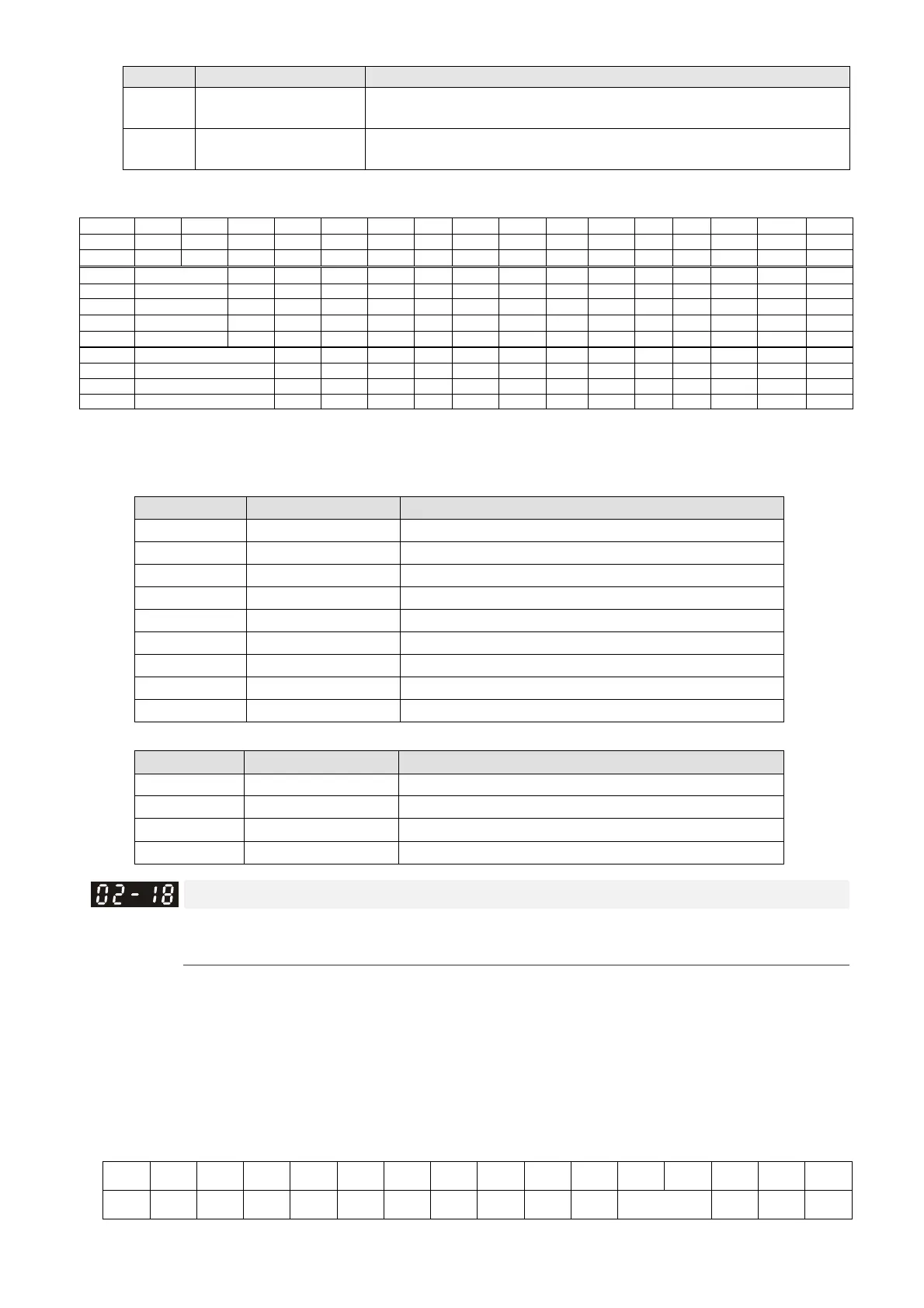
Remote IO function is added to directly make the drive control its AO/DO and read current AI/DI
status through the standard Modbus. The corresponding index of 26xx is as follows.
bit15 bit14 bit13 bit12 bit11 bit10 bit9 bit8 bit7
bit6 bit5 bit4 bit3 bit2 bit1 bit0
2600h MI15 MI14 MI13 MI12 MI11 MI10 MI8 MI7 MI6
MI5 MI4 MI3 MI2 MI1 REV FWD
2640h - - - - - MO15 MO14 MO13 MO12 MO11 MO10
- - RY3 RY2 RY1
2660h AVI1
- - - - - - - - - - - - - -
2661h ACI
- - - - - - - - - - - - - -
2662h AVI2
- - - - - - - - - - - - - -
266Ah AI10
- - - - - - - - - - - - - -
266Bh AI11
- - - - - - - - - - - - - -
26A0h AFM1
- - - - - - - - - - - - -
26A1h AFM2
- - - - - - - - - - - - -
26AAh AO10
- - - - - - - - - - - - -
26ABh AO11
- - - - - - - - - - - - -
In addition, the AI and DI values can be read directly, and DO and AO have to be controlled by
Modbus for corresponding parameter functions. The tables below shown the related parameter
definition.
DO
Terminal Pr. Setting Direct control the index corresponded to Modbus
RY1 Pr.02-13 = 51 bit0 of 2640h
RY2 Pr.02-14 = 51 bit1 of 2640h
RY3 Pr.02-15 = 51 bit2 of 2640h
MO10 / RY10 Pr.02-36 = 51 bit5 of 2640h
MO11 / RY11 Pr.02-37 = 51 bit6 of 2640h
MO12 Pr.02-38 = 51 bit7 of 2640h
MO13 Pr.02-39 = 51 bit8 of 2640h
MO14 Pr.02-40 = 51 bit9 of 2640h
MO15 Pr.02-41 = 51 bit10 of 2640h
AO
Terminal Pr. Setting Direct control the index corresponded to Modbus
AFM1 Pr.03-20 = 21 The value of 26A0h
AFM2 Pr.03-23 = 21 The value of 26A1h
AFM10 Pr.14-12 = 21 The value of 26AAh
AFM11 Pr.14-13 = 21 The value of 26ABh
Multi-function Output Direction
Default: 0000h
Settings 0000h–FFFFh (0: N.O.; 1: N.C.)
This parameter is in hexadecimal.
This parameter is set by a bit. If the bit is 1, the corresponding multi-function output acts in an
opposite way.
Example: Assume Pr.02-13=1 (indication when the drive is operating). If the output is positive, the
bit is set to 0, and then Relay is ON when the drive runs and is OFF when the drive stops. On the
contrary, if the output is negative, and the bit is set to 1, then the Relay is OFF when the drive
runs and is ON when the drive stops.
bit15 bit14 bit13 bit12 bit11 bit10 bit9 bit8 bit7 bit6 bit5 bit4 bit3 bit2 bit1 bit0
MO20 MO19 MO18 MO17 MO16 MO15 MO14 MO13 MO12 MO11 MO10 Reserved RY3 RY2 RY1

 Loading...


