Chapter 16 PLC Function Applications│CP2000
16-11
Basic Operation-Example
Input the ladder diagram as the figure below. The following steps can be operated through the mouse
or function key (F1–F12) on the keyboard.
Figure 16-10
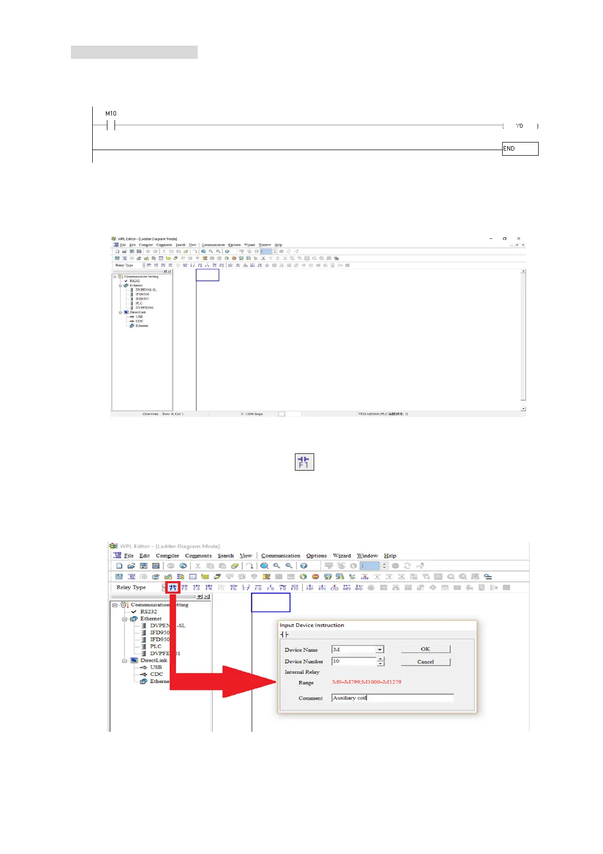
Step 1: The following screen will appear after a new file is established:
Figure 16-11
Step 2: Click on the always-open switch icon
or press the function key F1. After the name of the
input device and the comment dialog box have appeared, the device name (such as "M"),
device number (such as "10"), and input comments (such as "auxiliary contact") can be
selected; press the OK button when finished (see figure 16-12 and 16-13 below).
Figure 16-12

 Loading...


