EasyManua.ls Logo

Delta R2-EC 004 Series - Connection Ports and Indicators

Delta R2-EC 004 Series
67 pages
To Next Page IconTo Next Page
To Previous Page IconTo Previous Page
Loading...
Specifications and Product Interface R2-ECx004 User Manual
2-6
2
2.4 Description of connection ports and indicators
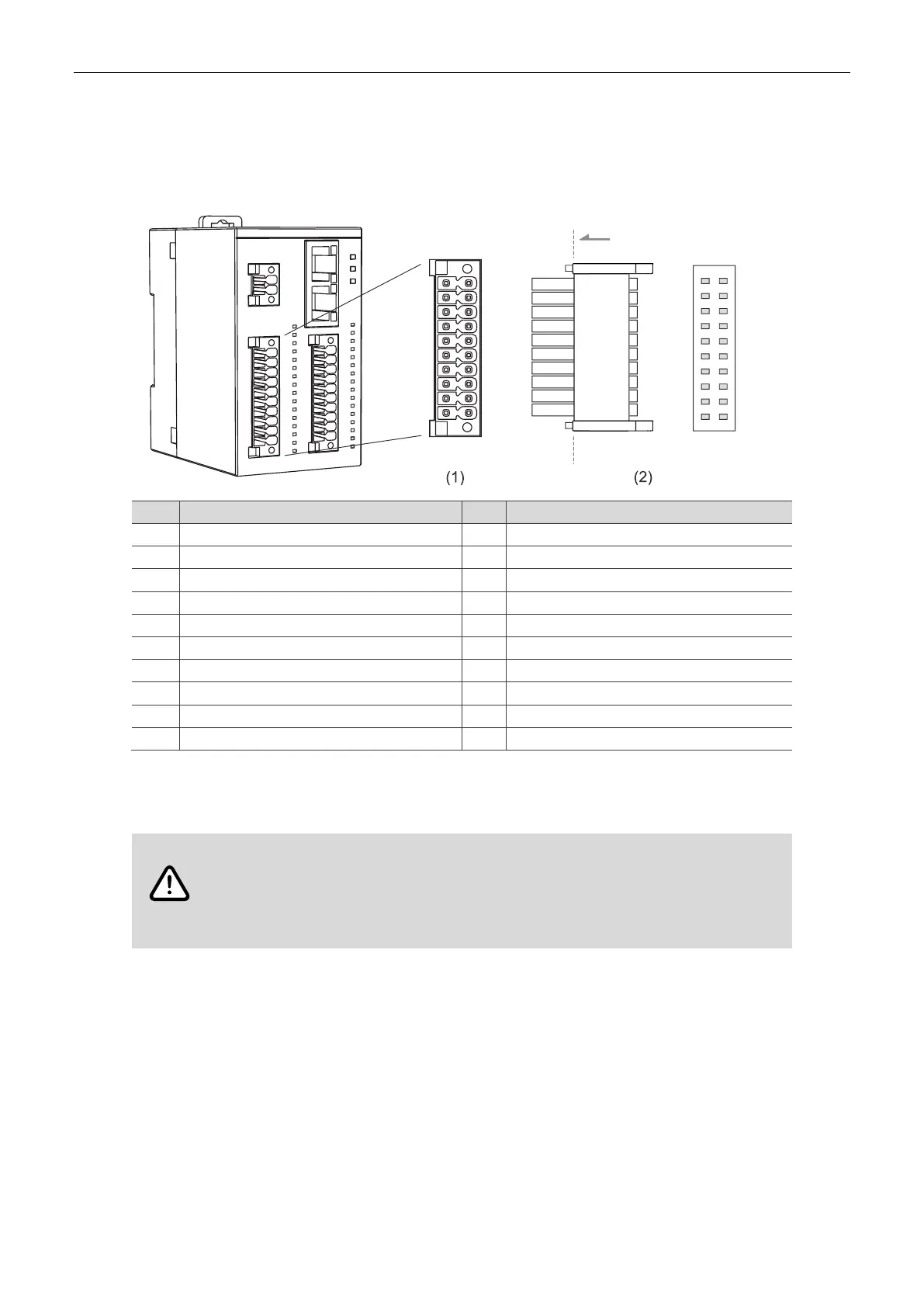
2.4.1 R2-ECx004 IO Port 0
Definitions of Port 0 for R2-EC0004 and R2-EC1004 models are as follows.
S/S
S/S
0
2
4
6
8
10
12
14
S/S
1
3
5
7
9
11
13
15
16DI-DC
PORT0
Pin
Description
Pin
Description
S/S*
Common input point
-
Reserved (no connection)
S/S*
Common input point
S/S*
Common input point
0
1
st
input of Port 0
1
2
nd
input of Port 0
2
3
rd
input of Port 0
3
4
th
input of Port 0
4
5
th
input of Port 0
5
6
th
input of Port 0
6
7
th
input of Port 0
7
8
th
input of Port 0
8
9
th
input of Port 0
9
10
th
input of Port 0
10
11
th
input of Port 0
11
12
th
input of Port 0
12
13
th
input of Port 0
13
14
th
input of Port 0
14
15
th
input of Port 0
15
16
th
input of Port 0
Note: S/S is the common input point for connecting the NPN type or PNP type load. When an NPN type
load is connected, S/S functions as Vcc. When a PNP type load is connected, S/S functions as GND.
WARNING
Follow the instructions for power supply and wiring to prevent any danger.
Use two independent 24 V
DC
power supplies for the module and the common input /
output points to ensure proper operation.
Use 26 - 18 AWG wires for wiring.

Table of Contents

Related product manuals