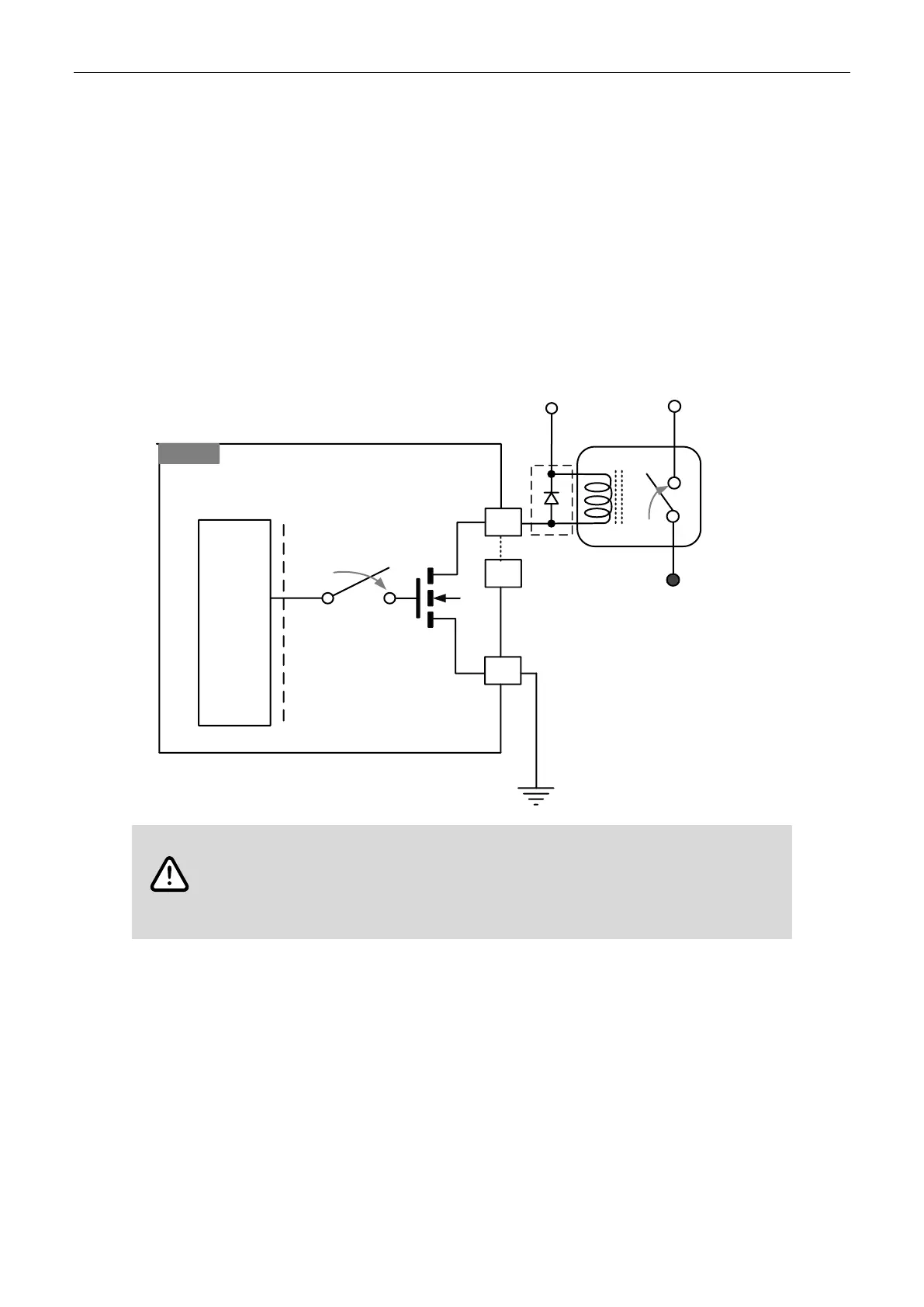
3.2 Output port wiring example
Connect NPN (SINK) type load to R2-ECx004 output ports
The IO power (IO_24V / IOGND) and module power (24VPWR / PWR_GND) should be two
independent power circuits.
The following figure illustrates a single output point (Y00). The structure is the same for the
other 15 output points (Y01 - Y15). Connect the GND of the output port to IOGND to avoid
output status error. If an inductive load is connected, ensure to connect a flyback diode to both
sides of the inductive load in parallel to protect the output circuit.
Follow these instructions for power supply and wiring to prevent any danger.
Use two independent 24 V
DC
power supplies for the module and the common input /
output points to ensure proper operation.
Use 26 - 18 AWG wires for wiring.
 Loading...