Chapter 5 Parameters|VFD-B-P Series
5-98 Revision April 2009, SW V1.00
10 - 04 Derivative Control (D) Unit: 0.01
Settings 0.00 to 1.00 sec Factory Setting: 0.00
This parameter specifies derivative control (rate of change of the input) and associated gain
(D). With this parameter set to 1, the PID output is equal to differential time x (present
deviation − previous deviation). It increases the response speed but it may cause over-
compensation.
10 - 05 Upper Bound for Integral Control Unit: 1
Settings 00 to 100 % Factory Setting: 100
This parameter defines an upper bound or limit for the integral gain (I) and therefore limits the
Master Frequency.
The formula is: Integral upper bound = Maximum Output Frequency (Pr.01-00) x (Pr.10-05)%.
This parameter can limit the Maximum Output Frequency.
10 - 06 Primary Delay Filter Time Unit: 0.1
Settings 0.0 to 2.5 sec Factory Setting: 0.0
To avoid amplification of measurement noise in the controller output, a derivative digital filter is
inserted. This filter helps to dampen oscillations.
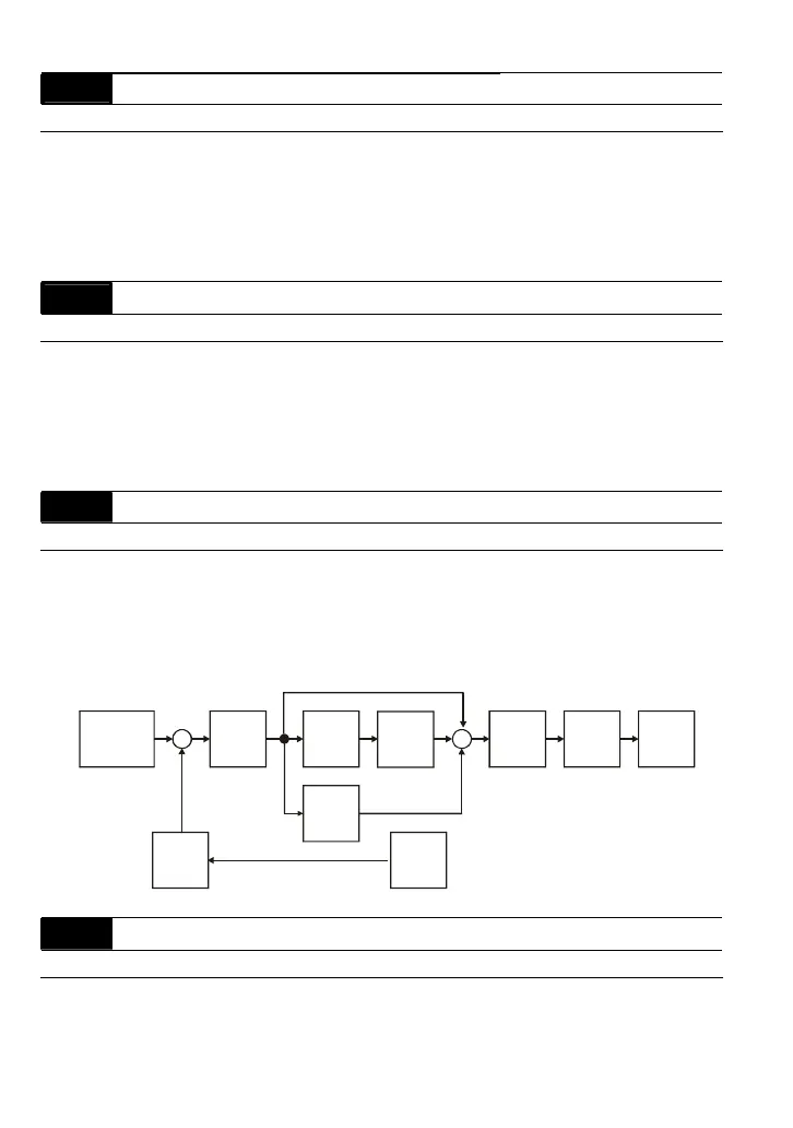
The complete PID diagram is shown on the following page:
P
10-02
I
10-03
D
10-04
10-05
10-01
10-07
10-06
10-00
+
-
+
+
+
Setpoint
Input Freq.
Gain
PID
feedback
Integral
gain
limit
Output
Freq.
Limit
Digital
filter
Freq.
Command
10 - 07 PID Output Frequency Limit Unit: 1
Settings 00 to 110 % Factory Setting: 100
This parameter defines the percentage of output frequency limit during the PID control. The
formula is Output Frequency Limit = Maximum Output Frequency (Pr.01-00) X Pr.10-07 %.

 Loading...


