Chapter 2 Installation and Wiring|VFD-B-P Series
2-28 Revision April 2009, SW V1.00
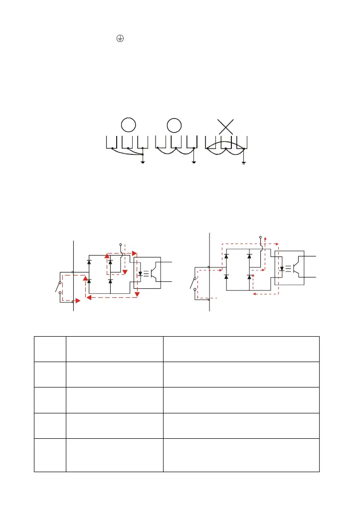
Grounding terminals ( )
Make sure that the leads are connected correctly and the AC drive is properly grounded.
(Ground resistance should not exceed 0.1
Ω
.)
Use ground leads that comply with local regulations and keep them as short as possible.
Multiple VFD-B-P units can be installed in one location. All the units should be grounded
directly to a common ground terminal, as shown in the figure below. Ensure there are no
ground loops.
goodexcellent
not allowed
2.4.4 Control Terminals
Circuit diagram for digital inputs (SINK current 16mA.)
+24
SINK Mode
multi-input
terminal
Internal Circuit
DCM
+24V
Multi-Input
Terminal
DCM
Internal Circuit
SOURCE Mode
Terminal symbols and functions
Terminal
Symbol
Terminal Function
Factory Settings (SINK)
ON: Connect to DCM
FWD Forward-Stop command
ON: Run in FWD direction
OFF: Stop acc. to Stop Method
REV Reverse-Stop command
ON: Run in REV direction
OFF: Stop acc. to Stop Method
JOG Jog command
ON: JOG operation
OFF: Stop acc. to Stop Method
EF External fault
ON: External Fault. Display “EF” and stop
acc. To Stop Method.
OFF: No fault

 Loading...


