Chapter 2 Installation and Wiring|VFD-B-P Series
Revision April 2009, SW V1.00 2-27
DO NOT connect phase-compensation capacitors or surge absorbers at the output terminals
of AC motor drives.
With long motor cables, high capacitive switching current peaks can cause over-current, high
leakage current or lower current readout accuracy. To prevent this, the motor cable should
be less than 20m for 3.7kW models and below. And the cable should be less than 50m for
5.5kW models and above. For longer motor cables use an AC output reactor.
Use a well-insulated motor, suitable for inverter operation.
Terminals [+1, +2] for connecting DC reactor
+1
Jumper
DC reactor
To improve the power factor and reduce harmonics, connect a DC reactor between terminals
[+1, +2]. Please remove the jumper before connecting the DC reactor.
NOTE
Models of 45kW and above have a built-in DC reactor.
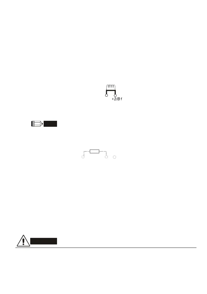
Terminals [+2/B1, B2] for connecting brake resistor and terminals [+1, +2/B1] for
connecting external brake unit
+2/B1
B2
-(minus si gn)
BR
Connect a brake resistor or brake unit in applications with frequent deceleration ramps, short
deceleration time, too low brake torque or requiring increased brake torque.
If the AC motor drive has a built-in brake chopper (all models of 11kW and below), connect
the external brake resistor to the terminals [
+
2/B1, B2].
Models of 15kW and above don’t have a built-in brake chopper. Please connect an external
optional brake unit (VFDB-series) and brake resistor. Refer to VFDB series user manual for
details.
Connect the terminals [+(P), -(N)] of the brake unit to the AC motor drive terminals
[+2(+2/B1), (-)]. The length of wiring should be less than 5m with twisted cable.
When not used, please leave the terminals [+2/B1, -] open.
WARNING!
1. Short-circuiting [B2] or [-] to [+2/B1] can damage the AC motor drive.

 Loading...


