Chapter 2 Installation and Wiring|VFD-B-P Series
Revision April 2009, SW V1.00 2-19
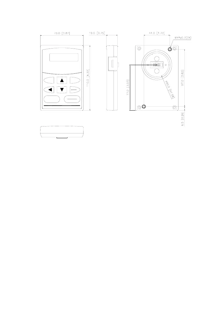
VFD-PU01
RUN
JOG
DATA
RESET
STOP
PROG
MODE
RUN
STOP
F
H
U
VFD- PU0 1
REVFWDJOG
2.4 Wiring
After removing the front cover, check if the power and control terminals are clear of debris. Be sure
to observe the following precautions when wiring.
2.4.1 Basic Wiring
Make sure that power is only applied to the R/L1, S/L2, T/L3 terminals. Failure to comply
may result in damage to the equipment. The voltage and current should lie within the range
as indicated on the nameplate.
Check the following items after completing the wiring:
1. Are all connections correct?
2. No loose wires?
3. No short-circuits between terminals or to ground?
A charge may still remain in the DC bus capacitors with hazardous voltages even if the power
has been turned off. To prevent personal injury, please ensure that the power is turned off
and wait ten minutes for the capacitors to discharge to safe voltage levels before opening the
AC motor drive.

 Loading...


