Appendix B Accessories|VFD-B-P Series
Revision April 2009, SW V1.00 B-5
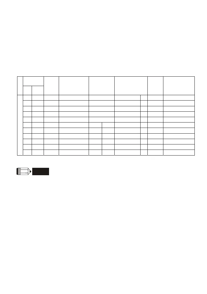
B.2 All Brake Resistors & Brake Units Used in AC Motor Drives
Note: Please only use DELTA resistors and recommended values. Other resistors and values will
void Delta’s warranty. Please contact your nearest Delta representative for use of special resistors.
For instance, in 460V series, 100hp/75kW, the AC motor drive needs 2 brake units with total of 16
brake resistors, so each brake unit uses 8 brake resistors. The brake unit should be at least 10 cm
away from AC motor drive to avoid possible interference. Refer to the “Brake Unit Module User
Manual” for further details.
Applicable
Motor
Voltage
hp kW
Full
Load
Torque
Nm
Resistor
value spec
for each AC
Motor Drive
Brake Unit
Part No. and
Quantity
Brake Resistors
Part No. and
Quantity
Brake
Torque
10%ED
Min. Equivalent
Resistor Value
for each AC
Motor Drive
3 2.2 1.262
300W 250Ω
BR300W250 1 125
160Ω
5 3.7 2.080
400W 150Ω
BR400W150 1 125
130Ω
7.5 5.5 3.111
500W 100Ω
BR500W100 1 125
91Ω
10 7.5 4.148
1000W 75Ω
BR1K0W075 1 125
62Ω
15 11 6.186
1000W 50Ω
BR1K0W050 1
125
39Ω
20 15 8.248
1500W 40Ω
4030 1
BR1K5W040 1
125
40Ω
25 18.5 10.281
4800W 32Ω
4030 1
BR1K2W008 4
125
32Ω
30 22 12.338
4800W 27.2Ω
4030 1
BR1K2W6P8 4
125
27.2Ω
40 30 16.497
6000W 20Ω
4030 1
BR1K5W005 4
125
20Ω
50 37 20.6
9600W 16Ω
4045 1
BR1K2W008 8
125
16Ω
460V Series
60 45 24.745
9600W 13.6Ω
4045 1
BR1K2W6P8 8
125
13.6Ω
NOTE
1. Please select the factory setting resistance value (Watt) and the duty-cycle value (ED%).
2. If damage to the drive or other equipment are due to the fact that the brake resistors and the
brake modules in use are not provided by Delta, the warranty will be void.
3. Take into consideration the safety of the environment when installing the brake resistors.
4. When using more than 2 brake units, equivalent resistor value of parallel brake unit can’t be
less than the value in the column “Minimum Equivalent Resistor Value for Each AC Drive” (the
right-most column in the table).
5. If the minimum resistance value is to be utilized, consult local dealers for the calculation of the
Watt figures.
6. For those applications needed to use with brake resistor or brake unit, it should disable Pr.06-
00 and also recommend to disable Pr.08-16 function.
7. Definition for Brake Usage ED%
Explanation: The definition of the barking usage ED(%) is for assurance of enough time for the
brake unit and brake resistor to dissipate away heat generated by braking. When the brake

 Loading...


