Chapter 2 Installation and Wiring|VFD-B-P Series
Revision April 2009, SW V1.00 2-21
AVI
ACI
AUI
ACM
+2/B1
B2
4~20mA
-10~+10V
+10V
5K
3
2
1
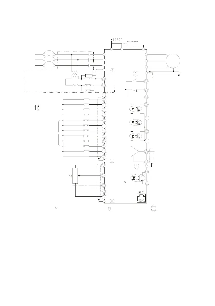
Figure 1 for models of VFD-B-P Serie
VFD022B43P-A
Jumper
Brake resistor
(optional)
Power supply
+10V 20mA
Master Frequency
0 to 10V 47 K
Analog Signal Common
DC choke
(optional)
E
Main circui t (power) terminals
Control circuit terminals
Shielded leads & Cable
FWD
REV
JOG
EF
MI1
MI2
MI3
MI4
MI6
TRG
MI5
DCM
+24V
Sw1
Sink
Source
Factory setting:
SINK Mode
FWD/STOP
REV/STOP
JOG
E.F.
Multi-step 1
Multi-step 2
Multi-step 3
Multi-step 4
RESET
Accel/Decel prohibit
Counter
Digital Signal Common
Factory
setting
* Don't apply the mains voltage directly
to above terminals.
E
Please refer to Figure 4
for w i ring of SINK
mode and SOURCE
mode.
R(L1)
S(L2)
T(L3)
Fuse/NFB(
None Fuse Breaker)
SA
OFF
ON
MC
MC
RB
RC
+1
Recommended Circuit when
power supply is turned OFF
by a fault output.
R(L1)
S(L2)
T(L3)
E
Analog Multi-function Output
Te r m in al
factory setting: Analog freq.
/ c ur re n t meter
0~10VDC/2mA
U(T1)
V(T2)
W(T3)
IM
3~
MO1
MO2
MO3
AFM
ACM
RA
RB
RC
MCM
RS-485
Motor
factory setting:
indicates during operation
48V50mA
factory setting:
Freq. Setting Indication
factory setting:
Low-voltage Indication
Multi-function
Photocoulper Output
Analog S ignal common
Serial interface
1: EV 2: GND
5:Reserved
6: Reserved
3: SG-
4: SG+
DFM
DCM
Digital Frequency Output
Te r m in al
factory setting: 1:1
Duty=50%
Digital Signal Common
48V50mA
48V50mA
E
E
Refer to Control
Ter minal Ex pl an a tion
* For the single phase drives, the A C input line can
be connected to any two of the three input terminals R,S,T
* Three phase input power may apply to single phase drives.
The contact will be ON
when the fault occurs to
turn off the power and
protect the power system.

 Loading...


