Chapter 2 Installation and Wiring|VFD-B-P Series
2-30 Revision April 2009, SW V1.00
Terminal
Symbol
Terminal Function
Factory Settings (SINK)
ON: Connect to DCM
MCM Multi-function output common Common for Multi-function Outputs
+10V Potentiometer power supply +10VDC 20mA (variable resistor 3-5kΩ)
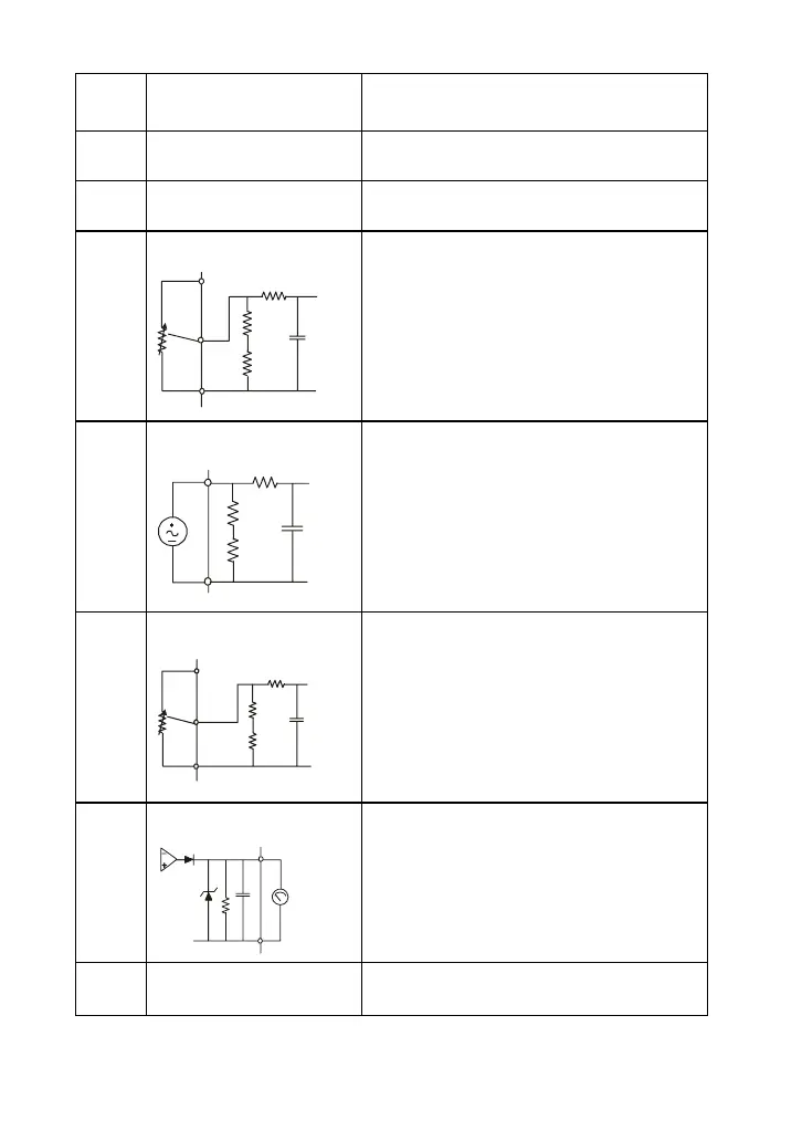
AVI
Analog voltage Input
ACM
AVI
+10V
internal circuit
AVI circuit
Impedance: 47kΩ
Resolution: 10 bits
Range: 0 ~ 10VDC =
0 ~ Max. Output
Frequency (Pr.01-00)
Selection: Pr.02-00, Pr.02-13,
Pr.10-00
Set-up: Pr.04-00 ~ Pr.04-03
ACI
Analog current Input
ACM
ACI
internal circuit
ACI circuit
Impedance: 250Ω
Resolution: 10 bits
Range: 4 ~ 20mA =
0 ~ Max. Output
Frequency (Pr.01-00)
Selection: Pr.02-00, Pr.02-13,
Pr.10-00
Set-up: Pr.04-11 ~ Pr.04-14
AUI
Auxiliary analog voltage input
ACM
AUI
+10
~
-10V
internal circuit
AUI circuit
Impedance: 47kΩ
Resolution: 10 bits
Range: -10 ~ +10VDC =
0 ~ Max. Output
Frequency (Pr.01-00)
Selection: Pr.02-00, Pr.02-13,
Pr.10-00
Set-up: Pr.04-15 ~ Pr.04-18
AFM
Analog output meter
AFM
ACM
0~10V
Max. 2mA
potentiometer
ACM circuit
internal circuit
0 to 10V, 2mA
Impedance: 470Ω
Output current 2mA max
Resolution: 8 bits
Range: 0 ~ 10VDC
Function: Pr.03-05
ACM
Analog control signal
(common)
Common for AVI, ACI, AUI, AFM
Control signal wiring size: 18 AWG (0.75 mm
2
) with shielded wire.
PLC1.ir

 Loading...


