Chapter 5 Parameters|VFD-B-P Series
5-24 Revision April 2009, SW V1.00
01 Display the actual output frequency (LED H)
02 Display the content of user-defined unit (LED U)
03 Multifunction display, see Pr.00-04
04 FWD/REV command
This parameter determines the start-up display page after power is applied to the drive.
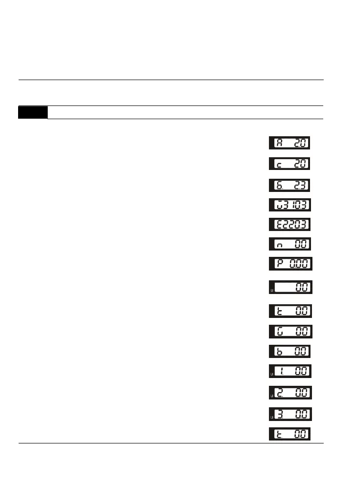
00 - 04 Content of Multi-Function Display
Factory Setting: 00
Settings 00 Display the output current in A supplied to the motor
01
Display the counter value which counts the number
of pulses on TRG terminal
02
When the PLC function is active, the current step and
its remaining operation time in s are shown.
03
Display the actual DC BUS voltage in VDC of the AC
motor drive
04
Display the output voltage in VAC of terminals U, V, W
to the motor.
05
Display the power factor angle in º of terminals U, V, W
to the motor.
06
Display the output power in kW of terminals U, V and W
to the motor.
07
Display the actual motor speed in rpm (enabled in
vector control mode or PG (Encoder) feedback control)
(LED H and LED U).
08
Display the estimated value of torque in Nm as it relates
to current.
09
Display PG encoder feedback pulses/10ms.
Display value= (rpm*PPR)/6000 (see note)
10 Display analog feedback signal value in %.
11
Display the signal of AVI analog input terminal in %.
Range 0~10V corresponds to 0~100%. (LED U)
12
Display the signal of ACI analog input terminal in %.
Range 4~20mA corresponds to 0~100%. (LED U)
13
Display the signal of AUI analog input terminal in %.
Range -10V~10V corresponds to 0~100%. (LED U)
14
Display the temperature of heat sink in °C.
This parameter sets the display when Pr. 00-03 is set to 03.

 Loading...


