Running the motor at low frequency for a long time reduces the cooling function of the motor fan.
To prevent overheating, use a Positive Temperature Coefficient thermistor on the motor, and
connect the thermistor output signal to the drive’s corresponding control terminals.
When you set the source of the first and second frequency command to AVI (Pr.02.00 = 1 /
Pr.02.09 = 1), you disable the motor PTC overheat protection (that is, Pr.07.12 cannot be set to
1).
If the temperature exceeds the setting level, the motor coasts to stop and PtC1 ( )
displays. When the temperature decreases below the level of (Pr.07.15 minus Pr.07.16) and
stops blinking, you can press the RESET key to clear the fault.
Pr.07.14 (overheat protection level) must be greater than Pr.07.15 (overheat warning level).
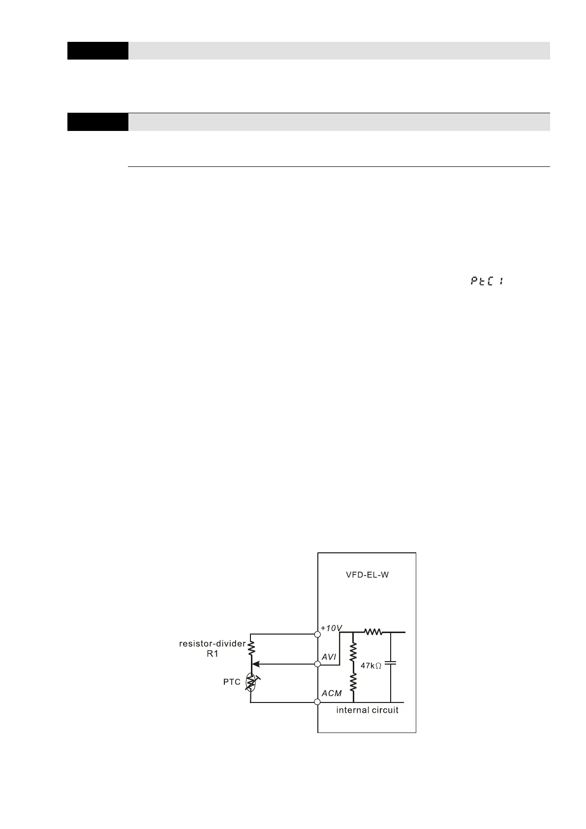
The PTC function uses the AVI, +10V and ACM terminals, when PTC enables (Pr.07.12 = 1), it
uses AVI as PTC input and is connected with a resistor-divider as shown in the diagram below.
1. The voltage between +10V to ACM: lies within 10.4–11.2V.
2. The internal impedance for AVI is around 47 kΩ Recommended value for divider resistance
is 1K–10K Ω.
3. Contact your motor dealer for the curve of temperature and resistance value for PTC.
Protection level: Pr.07.14 = V+10 × (R
PTC1
//47k) ÷ [R1+ (R
PTC1
//47k)]
Warning level: Pr.07.15 = V+10 × (R
PTC2
//47k) ÷ [R1+ (R
PTC2
//47k)]
V+10: voltage between +10V-ACM actual value;
R
PTC1
: motor PTC overheat protection level; R
PTC2
: motor PTC overheat warning level
47 kΩ: the AVI input impedance; R1: divider resistance (recommended value: 1–10k Ω)
Take the standard PTC thermistor as an example: if the protection level is 1330 Ω, the actual
voltage between +10V-ACM is 10.5 V and divider resistance R1 is 4.4k Ω.
 Loading...


