EasyManua.ls Logo

Delta VFD-EL-W Series - Page 14

Delta VFD-EL-W Series
217 pages
To Next Page IconTo Next Page
To Previous Page IconTo Previous Page
Loading...
Chapter 1 IntroductionVFD-EL-W
9
Minimum Mounting Clearance
(Blue arrow) Inflow
(Red arrow) Outflow
(Black) Distance
Single Drive Installation
Side-by-Side Horizontal Installation
Zero-stack Installation
Model Name
Installation
Method
Minimum Distance
(mm)
Temperature °C
A
B
C
Note 1
Max.(Derating is not
required)
Max.(Derating is
required)
Note 3
VFD007EL21W(-1)
Single Drive
120
50
-
40
50
Side-by-Side
Horizontal
120
50
30
40
50
Zero-stack
Note 2
-
-
-
-
-
VFD007EL43W(-1)
VFD015EL43W(-1)
Single Drive
120
50
-
50
60
Side-by-Side
Horizontal
120
50
30
50
60
Zero-stack
-
-
-
-
-
VFD015EL21W(-1)
VFD022EL21W(-1)
VFD022EL43W(-1)
VFD040EL43W(-1)
VFD055EL43W(-1)
Single Drive
150
50
-
50
60
Side-by-Side
Horizontal
150
50
30
50
60
Zero-stack
150
50
0
40
50
NOTE:
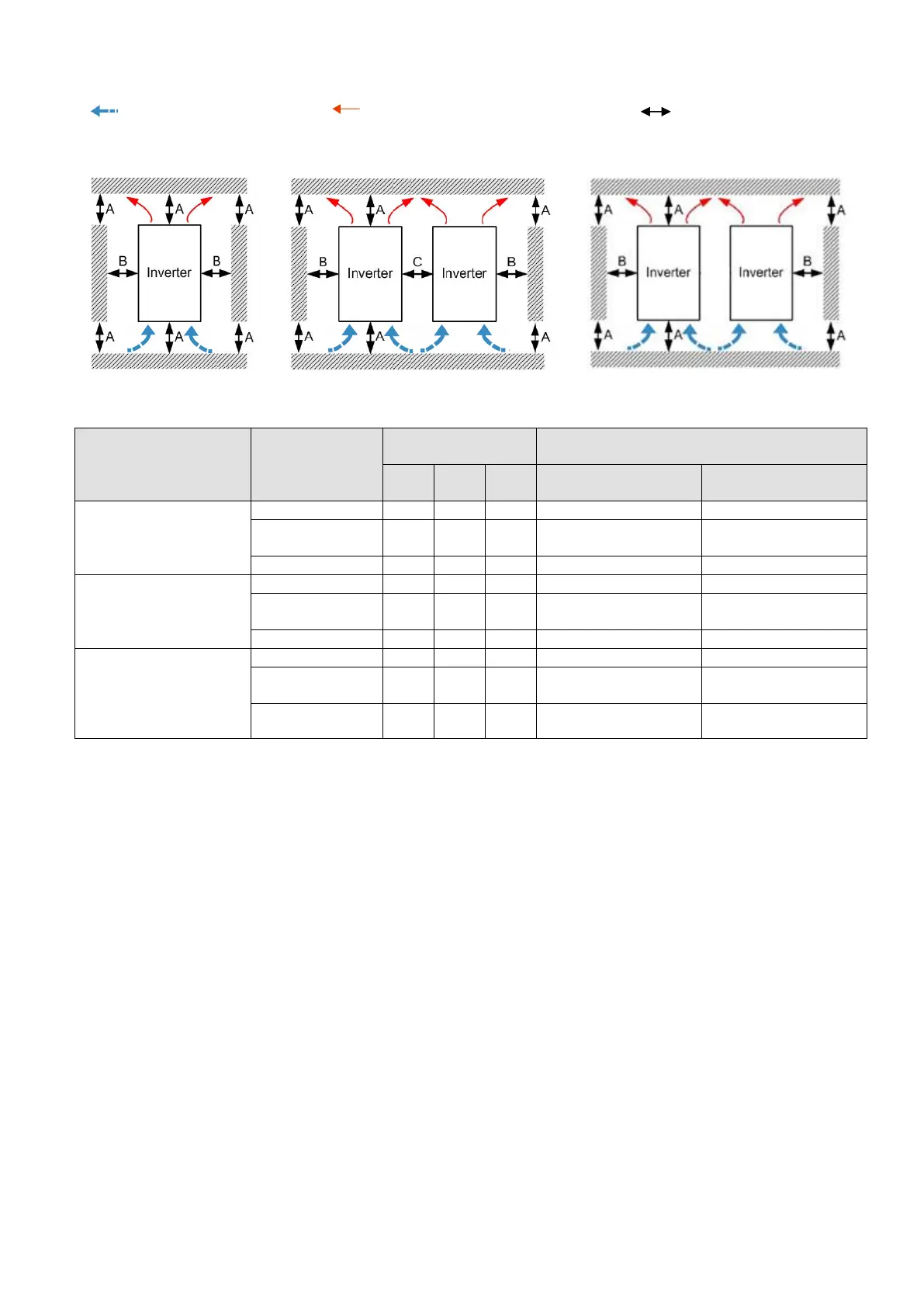
1. Due to a small protruding part of the heat sink at the bottom of the Frame A1/ A2, we calculate the distance C
for the side-by-side horizontal installation according to the main part of the motor drive only.
2. Frame A1 and A2 does not support zero-stack installation, whereas Frame B supports zero-stack installation.
3. Running the drive continuously with full load by the ambient temperature listed in the “Max. (derating)column
reduces the drive’s life span.
4. Install the drive vertically to achieve the optimal heat dissipation performance.
5. The back surface of the drive for installation must be a metal material with higher temperature endurance and
good heat dissipation.

Other manuals for Delta VFD-EL-W Series

Related product manuals