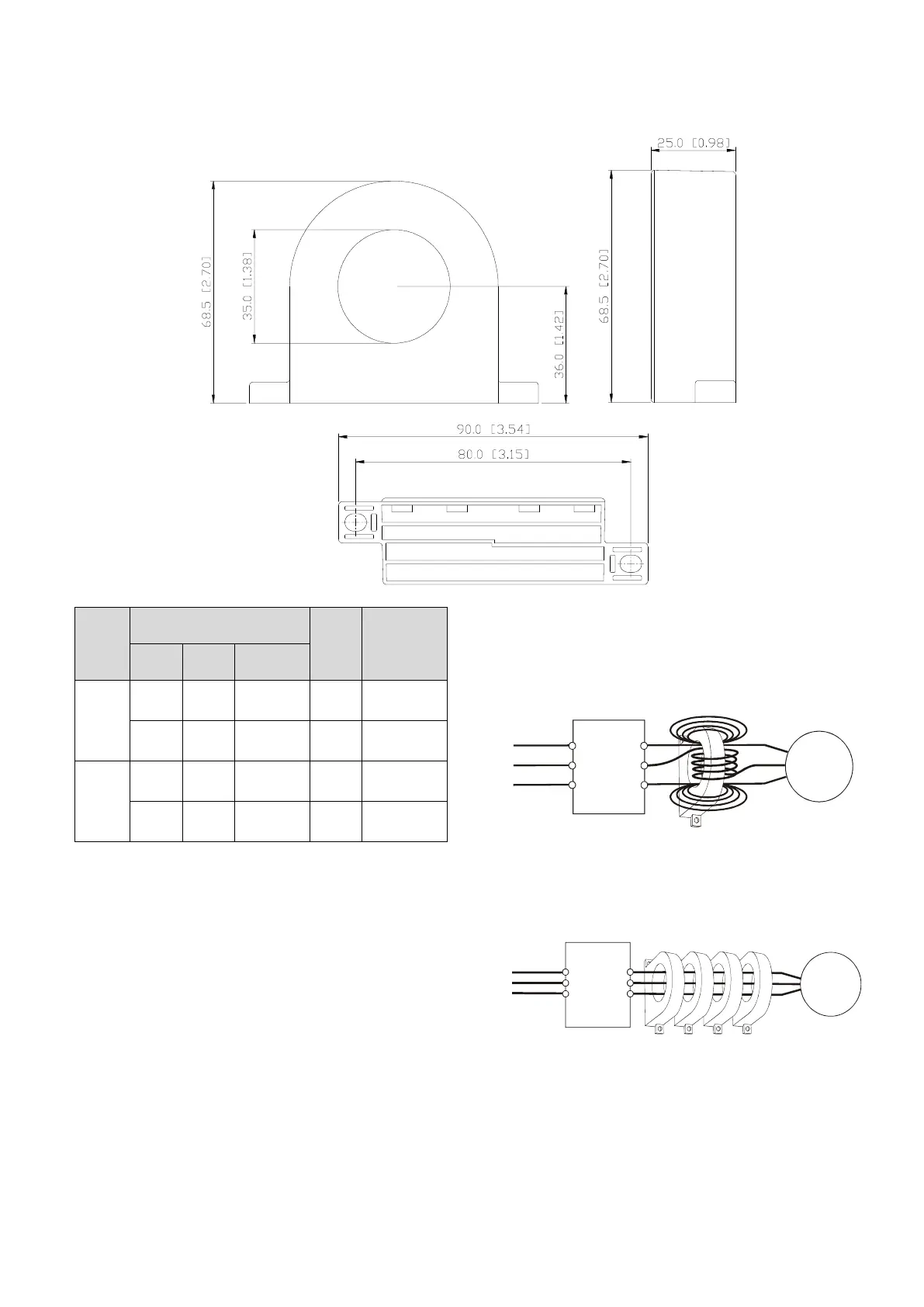
EasyManua.ls Logo

Delta VFD-EL-W Series - Page 202

Delta VFD-EL-W Series
217 pages
To Next Page IconTo Next Page
To Previous Page IconTo Previous Page
Loading...
Appendix B. Accessories VFD-EL-W
197
B-2-2 Zero Phase Reactor
RF220X00A
UNIT: mm [inch]
Cable
Type
(Note)
Recommended Wire
Size
Qty.
Wiring
Method
Diagram A
Please wind each wire four times around the core. The
reactor must be put as close to the inverter output as
possible.
Power
Supply
Zero Phase Reactor
MOTOR
U/T1
V/T2
W/T3
R/L1
S/L2
T/L3
AWG
mm
2
Nominal
(mm
2
)
Single-
core
10
5.3
5.5
1
Diagram A
2
33.6
38
4
Diagram B
Three-
core
12
3.3
3.5
1
Diagram A
1
42.4
50
4
Diagram B
NOTE:
600V Insulated Unshielded Cable
1. The table above gives approximate wire size for
zero phase reactors, but the selection is ultimately
governed by the type and diameter of the cable;
that is, the cable must fit through the center hole
of zero phase reactors.
2. When wiring, do not pass the grounding cable
through the zero phase reactor; only pass the
motor wire or power cable through the zero phase
reactor.
3. With longer motor cables the zero-phase reactor
can effectively reduce interference at the motor
output.
Diagram B
Please put all wires through four cores in series without
winding.
U/T1
V/T2
W/T3
R/L1
S/L2
T/L3
Power
Supply
Zero Phase Reactor
MOTOR

Other manuals for Delta VFD-EL-W Series

Related product manuals