Chapter 4 Parameters|VFD-EL-W
65
To write all parameters, set Pr.00.02 = 0.
7: Long press the ENTER key for 5 sec. to lock the keypad and setting knob. When the
frequency command source is the keypad potentiometer (Pr.02.00 = 4), set Pr.00.02 = 7 after
setting the required frequency command, then the keypad potentiometer does not change the
drive’s frequency command.
8: Long press the ENTER key for 5 sec. to lock the keypad. Long press ENTER key for 5 sec.
again to unlock the keypad.
Determines the start-up display page after power is applied to the drive.
Gets into the self-check state first when the drive starts-up, after displays “Pon” and flashes for 5
sec., the drive turns to start-up page.
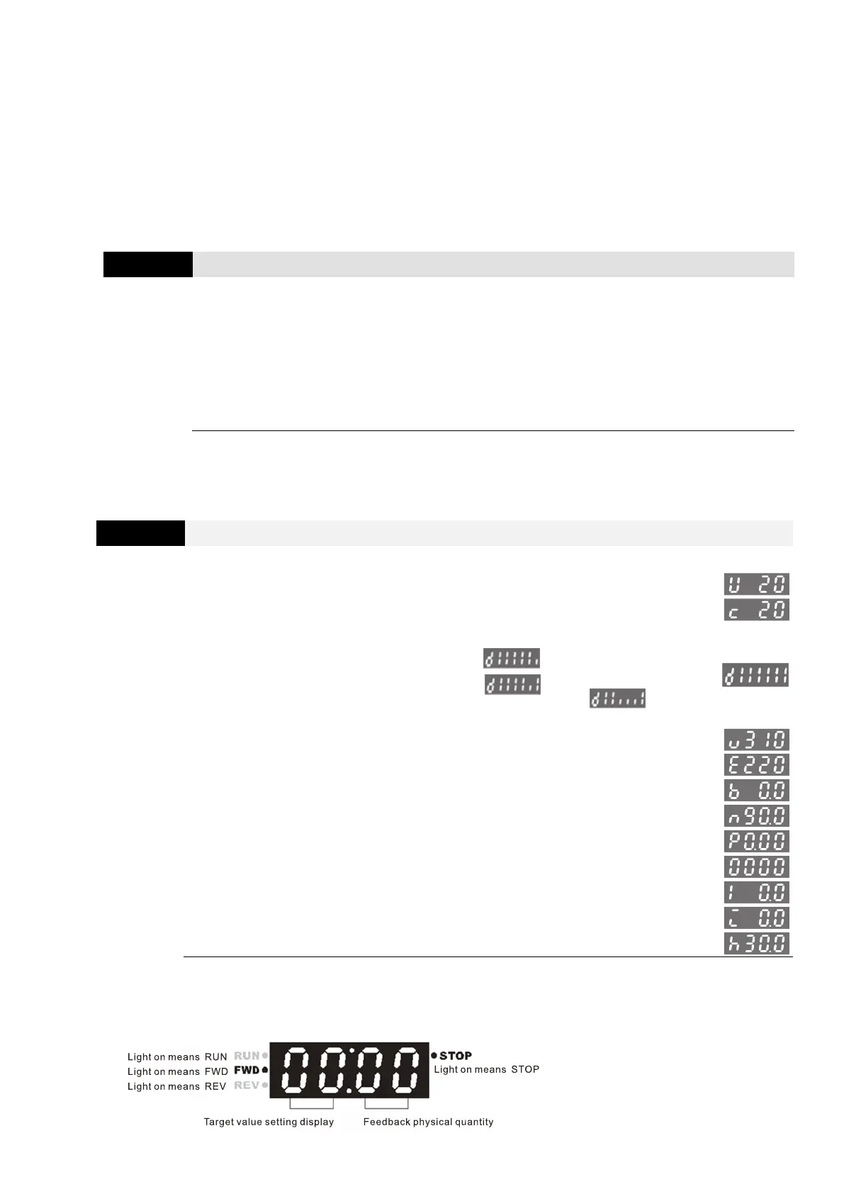
Content of Multi-function Display (User-Defined)
0: Display the content of user-defined unit
1: Display counter value (c)
2: Display the status of multi-function input terminal (d)
For example
Only MI1 terminal activates:
Only MI2 terminal activates:
MI2, MI3 and MI4 operate at the same time:
By analogy, MI1–MI4 are displayed in order from left to right
3: Display the drive's DC bus voltage (u)
4: Display the drive’s output voltage (E)
5: Display PID analog feedback signal (b)
6: Display the drive's power factor angle (n)
7: Display the drive’s output power (P)
8: Display the setting value and the feedback of PID control (P)
9: Display AVI analog input terminal signal (V) (I)
10: Display ACI analog input terminal signal (mA/V) (i)
11: Display IGBT temperature (°C) (h)
When Pr.00.03 is set to 3, use Pr.00.04 to select the displayed content as needed.
When Pr.00.04 = 5, the displayed PID feedback value is the percentage (%) of the terminal
measurement range.
 Loading...


