Chapter 5 Parameters_VFD-B Series
5-94
Revision 10/2005, BE13, SW V4.08
3. Communication Protocol
3.1 Communication Data Frame:
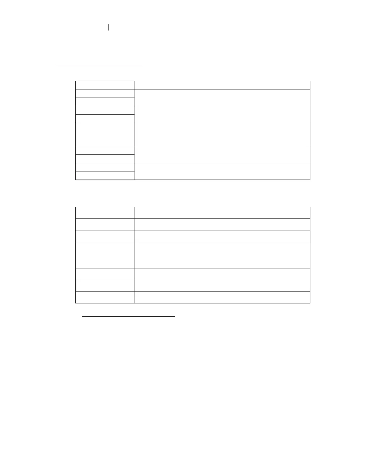
ASCII mode:
STX Start character ‘:’ (3AH)
Address Hi
Address Lo
Communication address:
8-bit address consists of 2 ASCII codes
Function Hi
Function Lo
Command code:
8-bit command consists of 2 ASCII codes
DATA (n-1)
to
DATA 0
Contents of data:
Nx8-bit data consist of 2n ASCII codes
n<=20, maximum of 40 ASCII codes
LRC CHK Hi
LRC CHK Lo
LRC check sum:
8-bit check sum consists of 2 ASCII codes
END Hi
END Lo
End characters:
END1= CR (0DH), END0= LF(0AH)
RTU mode:
START A silent interval of more than 10 ms
Address Communication address: 8-bit address
Function
Command code: 8-bit command
DATA (n-1)
to
DATA 0
Contents of data:
nÈ8-bit d ata, n<=40 (20 x 16-bit data)
CRC CHK Low
CRC CHK High
CRC check sum:
16-bit check sum consists of 2 8-bit characters
END A silent interval of more than 10 ms
3.2 Address (Communication Address)
Valid communication addresses are in the range of 0 to 254. A communication address equal to 0,
means broadcast to all AC drives (AMD). In this case, the AMD will not reply any message to the
master device.
00H: broadcast to all AC drives
01H: AC drive of address 01
0FH: AC drive of address 15
10H: AC drive of address 16
:
FEH: AC drive of address 254