Chapter 7 Optional AccessoriesC2000 Plus
7-66
Model* Recommended wire size Wiring method Q’ty
Applicable cables
T60006L2050W565 ≤ 1 AWG Diagram D 1 D-sub
T60006L2040W453 ≤ 8 AWG Diagram C 1
Category 5e shielding、Shielded
twisted pair cable、CAN standard cable
(TAP-CB05, TAP-CB10)
T60004L2025W622 ≤ 10AWG Diagram E 1
PG card signal cable
T60004L2016W620 ≤ 12AWG Diagram E 1 PG card signal cable
NOTE:
1. Mark * means that the table above is for reference only, select the zero phase reactor based on the
actual wire size that you are using.
2. Some of the cables are recommended to choose bigger zero phase reactor due to its corresponded
mechanical size.
Recommended max. motor cable size of zero phase reactor (included LUG width and temperature
tolerance of motor cable)
Zero phase reactor
Available max.
wire size/ LUG
width
Available max. AGW (1C*3) Available max. AWG (4C*1)
75C 90C 75C 90C
RF008X00A 13 mm 3 AWG 1 AWG 3 AWG 1 AWG
RF004X00A 16 mm 1 AWG 2/0 AWG 1 AWG 1/0 AWG
RF002X00A 36 mm 600 MCM 600 MCM 1 AWG 1/0 AWG
RF300X00A 73 mm 650 MCM 650 MCM 300 MCM 300 MCM
T60006L2040W453 11 mm 9 AWG 4 AWG 6 AWG 6 AWG
T60006L2050W565 16 mm 1 AWG 2/0 AWG 1 AWG 1/0 AWG
T60006L2160V066 57 mm 600 MCM 600 MCM 300 MCM 300 MCM
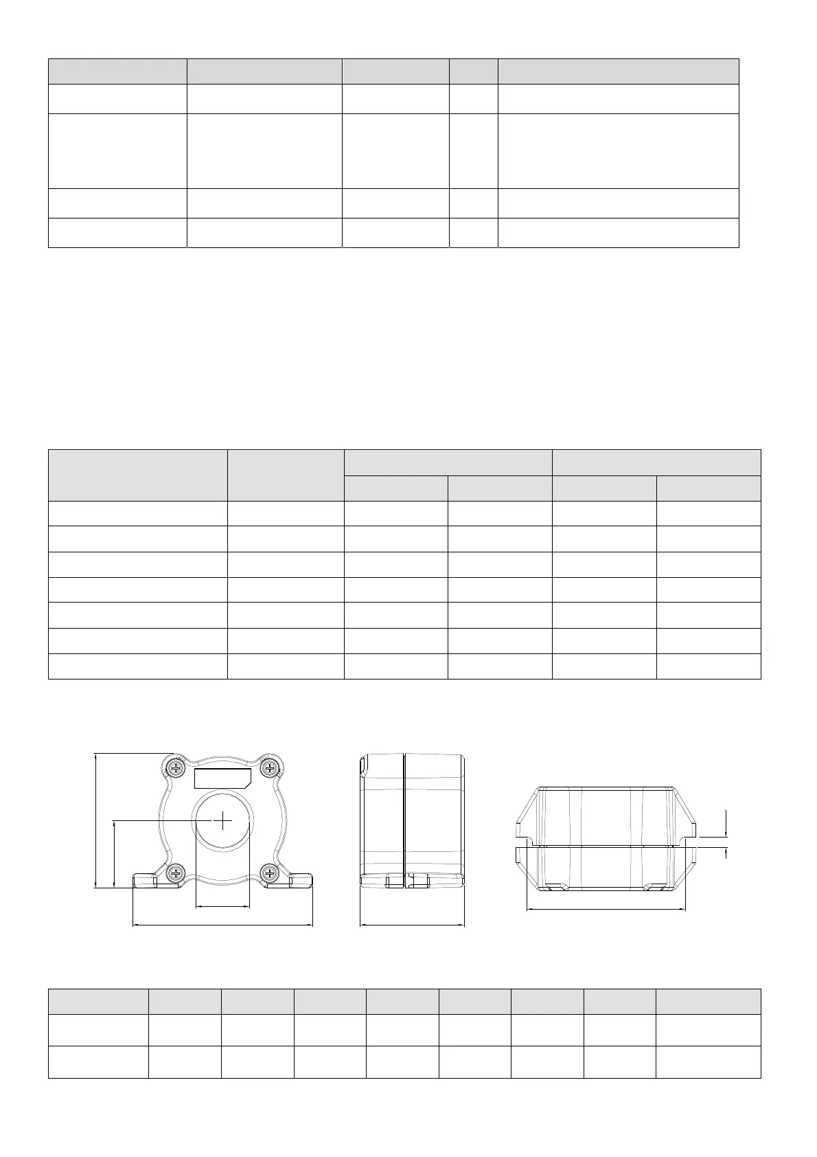
A
D
C
B
E
G
F
Figure 7-44
Unit: mm (inch)
Model A B C D E F G(Ø) Torque
RF008X00A
98
(3.858)
73
(2.874)
36.5
(1.437)
29
(1.142)
56.5
(2.224)
86
(3.386)
5.5
(0.217)
< 10 kgf/cm
2
RF004X00A
110
(4.331)
87.5
(3.445)
43.5
(1.713)
36
(1.417)
53
(2.087)
96
(3.780)
5.5
(0.217)
< 10 kgf/cm
2
Table 7-72
Table 7-73
Table 7-74
 Loading...
