EasyManuals Logo

DEMA 400 Series User Manual

DEMA 400 Series
118 pages
To Next Page IconTo Next Page
To Previous Page IconTo Previous Page
Page #93 background imageLoading...
Page #93 background image
93
curve type and performs a trip after the operation delay time. The direction of the protection is
determined using the direction angle value under protection settings.
Directional Active Over Power is indicated by P>, P>> in IEC 60617; PI_PDOP_1 ve
PI_PDOP_2 in IEC 61850; 32OP-I-1 ve 32OP-I-2 in IEEE/ANSI Standards
Directional Active Over Power
IEC 61850
IEC 60617
IEEE-ANSI
-1
PI_PDOP_1
P>
32OP-I-1
-2
PI_PDOP_2
P>>
32OP-I-2
Directional Active Over Power Function Symbols
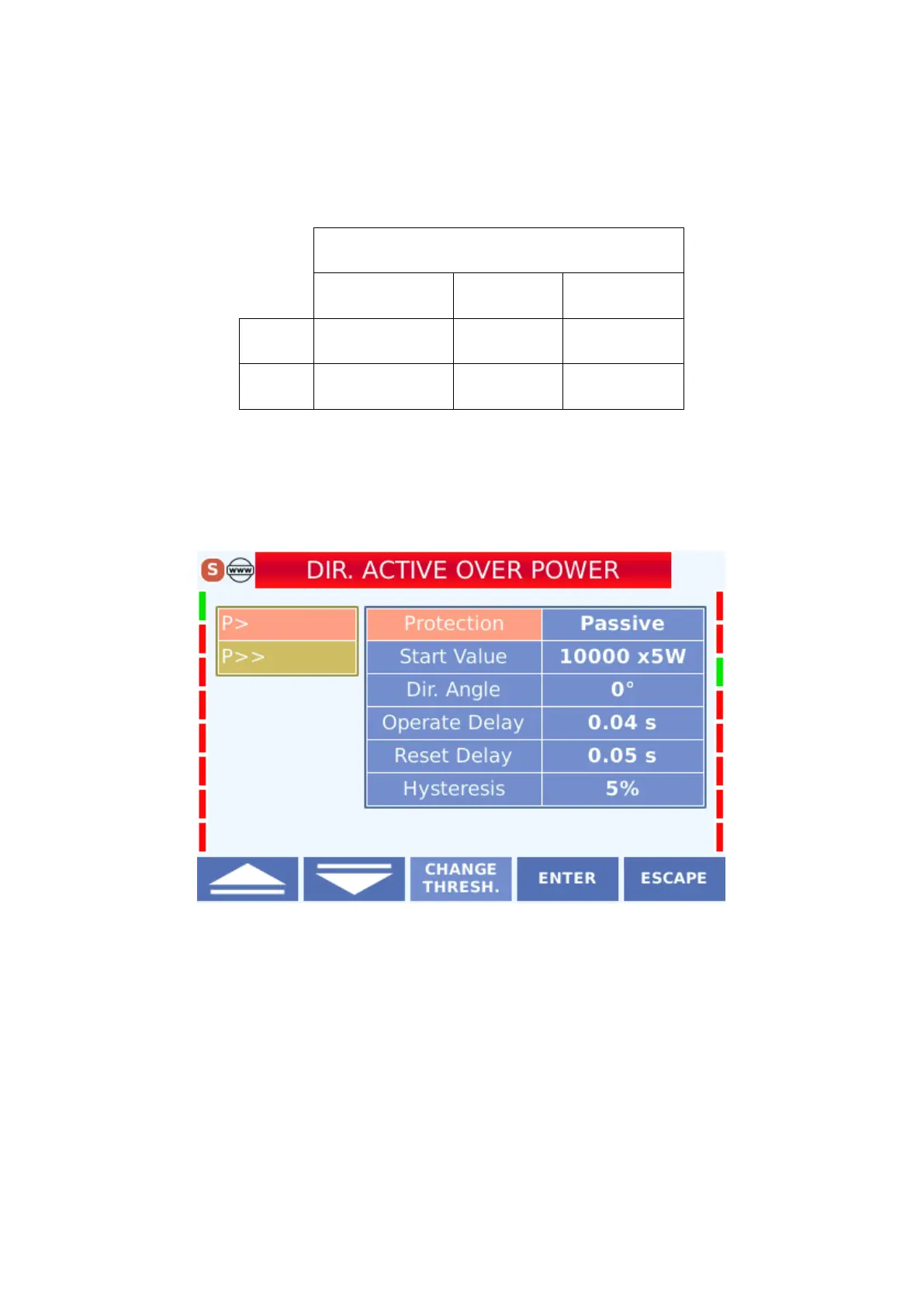
The menu view is as follows. The menu consists of six lines.
Directional Active Over Power Protection Display
The settings that can be made in the menu are described below.
4.3.5.1.1 Protection
on is
activated in the active state and disabled in the passive state
4.3.5.1.2 Start Value

Table of Contents

Questions and Answers:

Question and Answer IconNeed help?

Do you have a question about the DEMA 400 Series and is the answer not in the manual?

DEMA 400 Series Specifications

General IconGeneral
BrandDEMA
Model400 Series
CategoryRelays
LanguageEnglish

Related product manuals