The D1000
Installation and
Service
Version 2.1
1 1
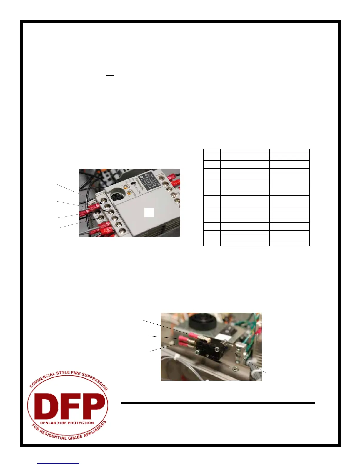
The hood unit has two re alarm connections (discrete switches), each with its own trigger. A connection is
made to one output (Y#) and one common (C#) at the PLC. The output labeled Y0 is triggered by a fault from
the low temperature switch (150 F), pressure switch, or hose switch. Output Y1 is triggered by a high tempera-
ture switch (190 F) and a low pressure fault in the extinguisher tank (the re suppressant has discharged). You
may use either one connection or both, depending on your situation. When there is a fault, a buzzer in the unit
will sound and the power disconnect will turn o.
Local Alarm Connection: Connect to output Y0 and common C0
Remote Alarm Connection: Connect to output Y1 and common C1
To connect to the alarms, it is preferred that you use a spade terminal connector (supplied), but a stripped wire
is acceptable.
Connecting the alarm system in the conguration described above results in a normally open connection.
In addition to the PLC connections above, a second connection may be made to the re alarm switch installed in the unit. Unlike the
connection above, this switch does not require power to be fed to the hood in order to function. The re alarm switch is located above the
actuactor arm, beside the PLC assembly. The re alarm switch is activated when the actuator arm trips.
To connect the re alarm switch, wire the re alarm to the common connector and normally open or normally closed connection as shown.
Fig: 14.1
C0
C1
Y0
Y1
PLC
Fire Alarm Switch
Common
Normally Open
Normally Closed
Fire Alarm System Connections
CB CLOCK BOX 2 HR
F1 PLC FUSE 1 AMP FAST BLOW
F2 FAN FUSE 2 AMP SLOW BLOW
F3 DUAL DISCONNECT 1 AMP SLOW BLOW
F3 DISCONNECT FUSE 0.5 AMP SLOW BLOW
F4 MAIN FUSE 8 AMP SLOW BLOW
F5 CLOCK BOX FUSE 8 AMP SLOW BLOW
MP1 MAIN POWER CONNECTOR
FP2 FAN CONNECTOR
SW1 MAIN POWER SWITCH
SW2 LIGHT SWITCH
SW3 SERVICE SWITCH
SW4 RESET SWITCH
SW5 OPTIONAL ADA LIGHT
SW6 OPTIONAL ADA FAN
HSW1 HOSE SWITCH
HITH1 HIGH TEMP THERMOSTAT 190°
LOTH1,2 LOW TEMP THERMOSTAT 150°
FSP1 FAN SPEED CONTROLLER 4.0 FLA
FAN INLINE OR RECIRC FAN
CAP1 FOR RECIRC FAN 10 UF
M1 STOVE DISCONNECT 40 FLA 50 A RES
LIGHT HOOD LIGHT 60 WATT
PLC COMPUTER DRIVING HOOD