The D1000
Installation and
Service
Version 2.1
22
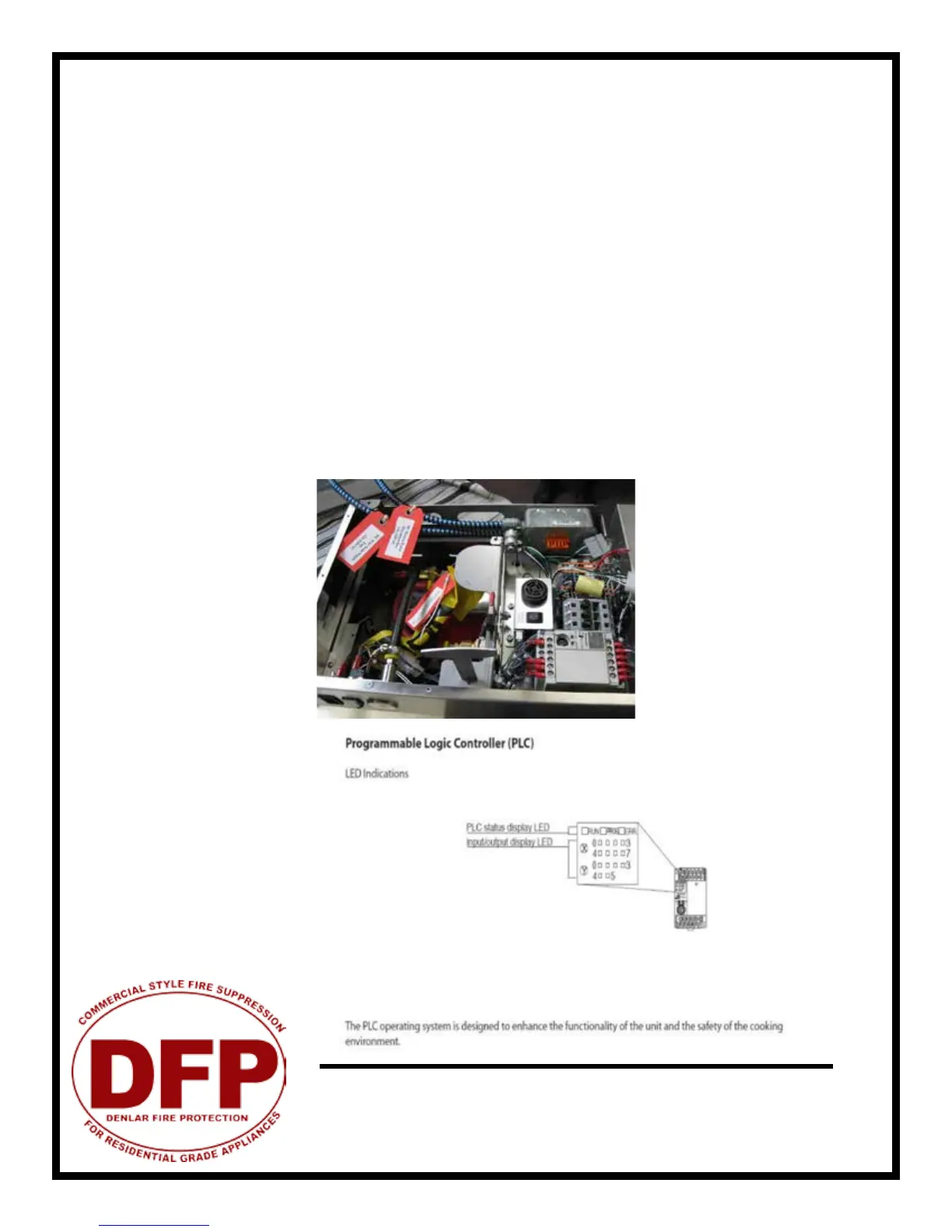
On the plc there are two rows of LED’s next to an X (inputs)
X0 hose switch (hose in place) LED on
X1 reset switch (this will be on when the reset switch is depressed)
X2 pressure switch (pressure ok) LED on
X3 service switch (should be off for normal operation)
X4 both low temp thermostats are in the normal position LED on
X5 will be off when the output for remote and local alarms are normally open (no jumper)
X6 high thermostat in the normal (not hot) LED on
There are two rows of LED’s on the Y area (outputs)
Y0 is alarm output for local alarm when the low gas switch activates, OR hose switch activates, OR the
high temp switch or red jumper activates
Y1 is alarm output when you lose pressure and have high temp
Y2 orange LED (should be off in normal condition)
Y3 fan (this will be on when the plc turns the fan on)
Y4 this is the output to the power disconnect or gas valve (will be on in normal mode) LED on
Y5 this is the output for the horn (this should be off normally)
PLC Schematic - LED Indicators