110VAC Supply from Hood
-Electrical Connection
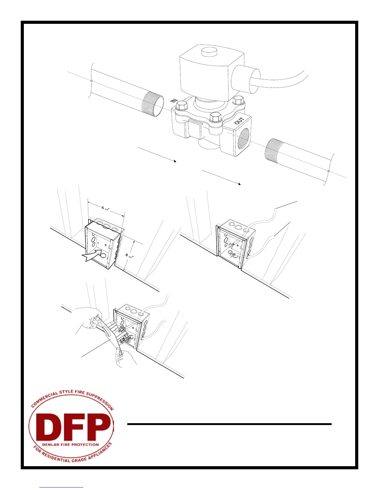
3/4” NPT
Gas Flow
3/4” NPT
Face Plate
The D1000
Installation and
Service
Version 2.1
8
1. Cut a hole in the drywall for the relay box; refer to the
specication sheets for dimensions. Be sure to note the
1
1
/
4
” overhang on each side of the face plate. Given this
the hole should be about 6 3/8” by 8 3/4”. The relay box
has been designed to t in a standard 2x4 studded wall.
2. If you havent already done so, run wiring from the
junction box location (on the unit mounting plate) to
the power disconnect box location and string through
one of the knockouts in the box.
3. Make all wiring connections and secure face plate to
box in wall.
The gas solenoid is designed for use
with 3/4” NPT pipe. Be sure to note
the “IN” and “OUT” ends of the sole-
noid body (as marked on the body).
This determines direction of gas ow.
Refer to wiring diagram for details on
electrical connection.
Range Element Disconnect Installation
Gas Disconnect Valve - G
Electrical Disconnect Box - E
208-220VAC (supply to stove)
120VAC (from hood - black tape)