The D1000
Installation and
Service
Version 2.1
7
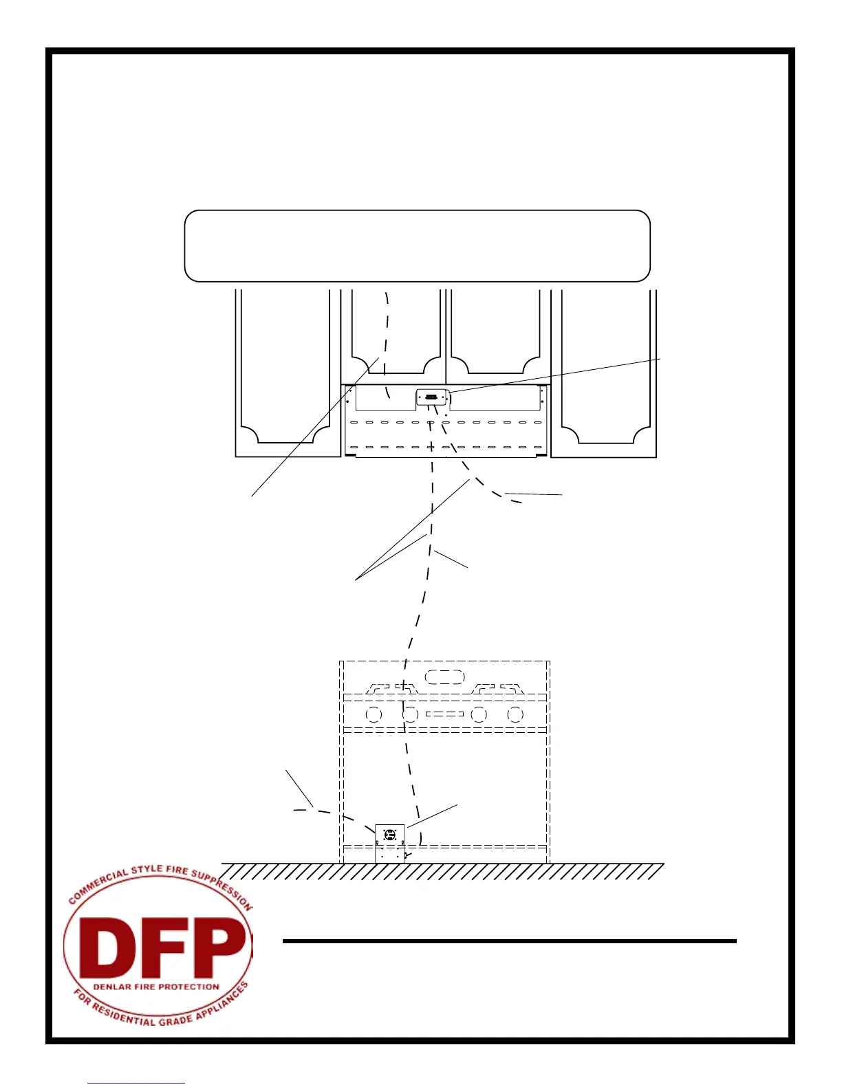
1. Determine mounting location of the power disconnect (contactor box or gas valve) and mounting bracket, if not already
done.
2. Run wire from junction box through the wall to the power disconnect location. Run MC wire for the 110VAC supply from
the junction box to the 110VAC connection. Refer to the wiring diagram on the following page for details on how to wire
the Power Disconnect Box.
3. If the hood unit is to be linked to a re alarm system, accomodations for those wires will need to be made at this time as
well. See re alarm appendix.
Power disconnect
moutned ush to
wall (50A 250V
NEMA 14-50
receptacle -
supplied by DFP)
Range Supply Line
208-220VAC 50A max
(not supplied by DFP)
Hood Supply 110-120VAC 15A
(Metal Clad Wire from 110-120
VAC Supply Line -12/2 8ft Length
-marked with red tape)
Junction Box with
Connector
Run MC wire from junction box
on mounting plate to power
disconnect box through wall
(Metal Clad Wire from 110-
120 VAC Supply Line -14/2 8ft
length -marked with black tape)
Alarm Wire(s)
NO/NC Local and
Remote Alarm
(Not Supplied by DFP)
Supplied by DFP
CAUTION: This should be performed by a licensed electrician. Installation
should be performed according to all applicable codes and regulations.
Shut o power at the main breaker to prevent electrical shock. Use metal
clad 12/2 (supplied) or replaced with wire specied by local building codes.