The D1000
Installation and
Service
Version 2.1
5
Preparing the Install Location
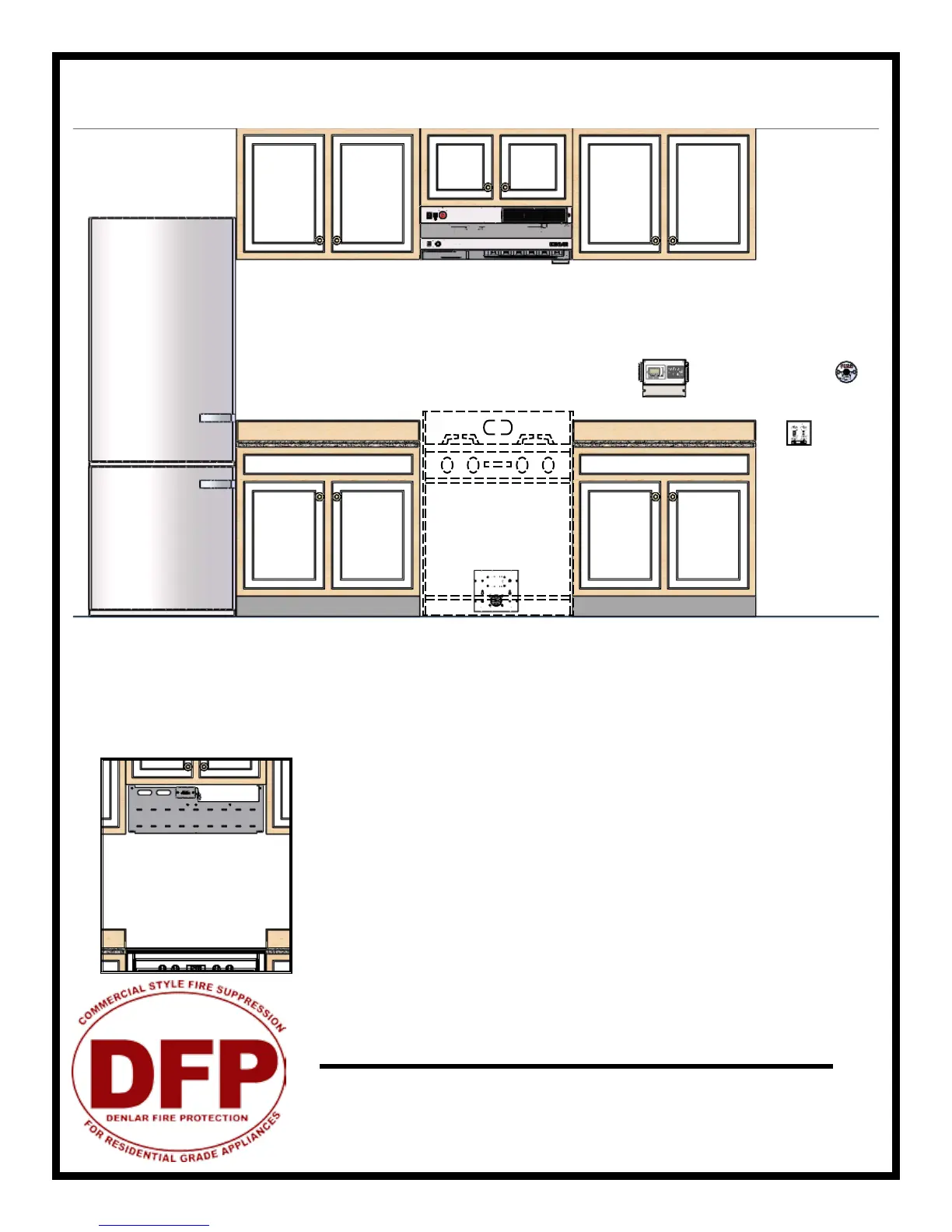
A
F
E
DC
B
G
Installation Elevation: KEY
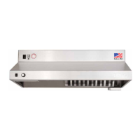
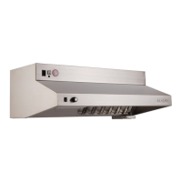
A. DENLAR D1000 (30” or 36”)
B. Stove (For Reference Purposes)
C. Electric Range Element Disconnect
D. Gas Range Element Disconnect (not shown)
E. e CLOCKBOX - Range Element Time-Out System (CLBX option)
F. Handicapped Accessible Control Box (ADA option)
G. Manual Pull Station (MPK option)
Note #1: If cabinettes are not present in the space, a Top Cover is recommended (option D1000-TC)
Note #2: Center the D1000 over the range. If the range is not inplace, the center marking should be relative to it’s nal position
Note #3: Refer to the model specic engineered submittal sheet for exact measurements not represented here (www.denlarhoods.com)
Note #4: Refer to “Installing e D1000” for instructions re: attaching the D1000 to the mounting bracket
Note #5: Refer to option specic installation instructions for more specic details on how to connect them to e D1000
Note #6: (Next Page) Allow for 4.535” between the top of the mounting bracket and the bottom of the cabinette above. e NFPA101
compliant version of the D1000-F/R uses an additional Fan Box as shown. Attach the fan box to the bracket, then proceed.
Note #5
Contact a DENLAR Distributor to discuss lead-ship delivery of the D1000’s
installation components. is may allow you to complete installation
connections, prior to delivery of the unit