The D1000
Installation and
Service
Version 2.1
2 7
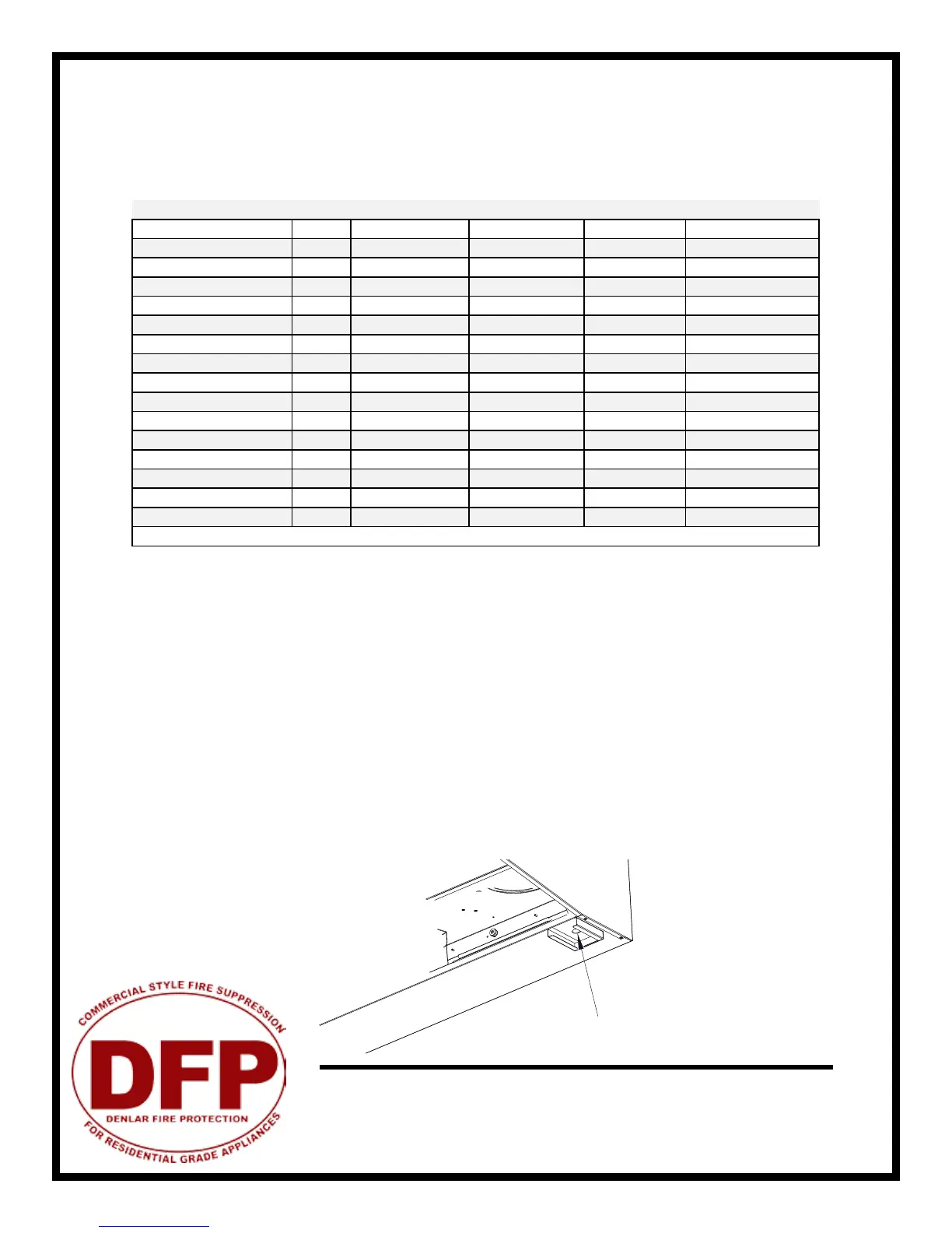
Magnehelic Gauge Test Port
The ductwork and ttings used for outside venting must be carefully selected to insure that the static pressure is
in line with the fan parameters.
Please see table below for maximum duct length and number of ttings allowed for the various fan options.
Width FanType Venting CFM(athood) DUCTLENGTH(max)
D1030F_ 30" INTERNAL FRONT(recirc) 140CFM N/A
D1030F_(NFPA101) 30" INTERNAL FRONT(recirc) 500CFM N/A
D1030R_ 30" INTERNAL REAREXPELLING 250CFM N/A
D1030R_(NFPA101) 30" INTERNAL REAREXPELLING 500CFM N/A
D1030I_DF 30" InLineDuctFan VertcalDuct 470CFM 35FEET
D1030I_DF(NFPA101) 30" InLineDuctFan VertcalDuct 510CFM 35FEET
D1030I_WF 30" ExteriorWallFan VertcalDuct 150CFM 20FEET
D1030I_WF(NFPA101) 30" ExteriorWallFan VertcalDuct 550CFM 20FEET
D1036F_ 36" INTERNAL FRONT(recirc) 140CFM N/A
D1036F_(NFPA101) 36" INTERNAL FRONT(recirc) 500CFM N/A
D1036R_ 36" INTERNAL REAREXPELLING 250CFM N/A
D1036R_(NFPA101) 36" INTERNAL REAREXPELLING 500CFM N/A
D1036I_DF 36" InLineDuctFan VertcalDuct 470CFM 35FEET
D1036I_DF(NFPA101) 36" InLineDuctFan VertcalDuct 510CFM 35FEET
D1036I_WF 36" ExteriorWallFan VertcalDuct 150CFM 20FEET
D1036I_WF(NFPA101) 36" ExteriorWallFan VertcalDuct 550CFM 20FEET
Volts=115::Hz=60Amps::LightBulb=60A15/TF::Elec.Cutoff=50A208VACRelay::GasCutoff=110VACSolenoid
WARNING: The amount of ttings and ductwork directly aects the resistance or static pressure placed on the
system. If the system is not within the proper static pressure range, the heat sensors and controls will be ad-
versely aected and will impact the proper functioning of the safety controls. Therefore it is required that air
ow testing be recorded along with install documentation. The air testing area is accessed by the removal of the
grease tray and measured with an air ow pressure gauge.
Static Pressure Testing
The magnehelic gauge test port opening is located beneath the grease tray. The static pressure needs to be
measured to ensure air ows meet design criteria. The airow is measured by attaching the gauge tubing to the
magnehelic gauge inlet, and the hood tting is attached to the grease drain hole beneath the grease tray.
A reading of 0.45” to 0.85” (of water) is required to meet design standards. This reading will correspond to the
static pressure of the ductwork, hood and fan combination. For other ductwork congurations not meeting the
above specications, please contact our engineering department and a custom solution can be developed.
Ducting & Airow