The D1000
Installation and
Service
Version 2.1
2 3
Alarm Outputs: The other function of the PLC is to report alarms from the system either for a system fault or as
a result of a system discharge. See Alarm Appendix in the installation manual for information on how to connect
the alarm outputs.
Output Y1 and common C1 are congured to close with the discharge of the extinguisher tank. This condition is
determined by the PLC with the low pressure input from the switch and a high temperature condition from the
190 rated thermostat. Both conditions must be present in order for this output to trigger.
Note that the microswitch outputs are dry contact type, rated for low voltage, and can be normally open (NO) or
normally closed (NC), with a common. Therefore do not produce any current or voltage output.
NOTE: Pressing the reset button will not turn o alarm. Unit needs to be
recharged to reset alarm.
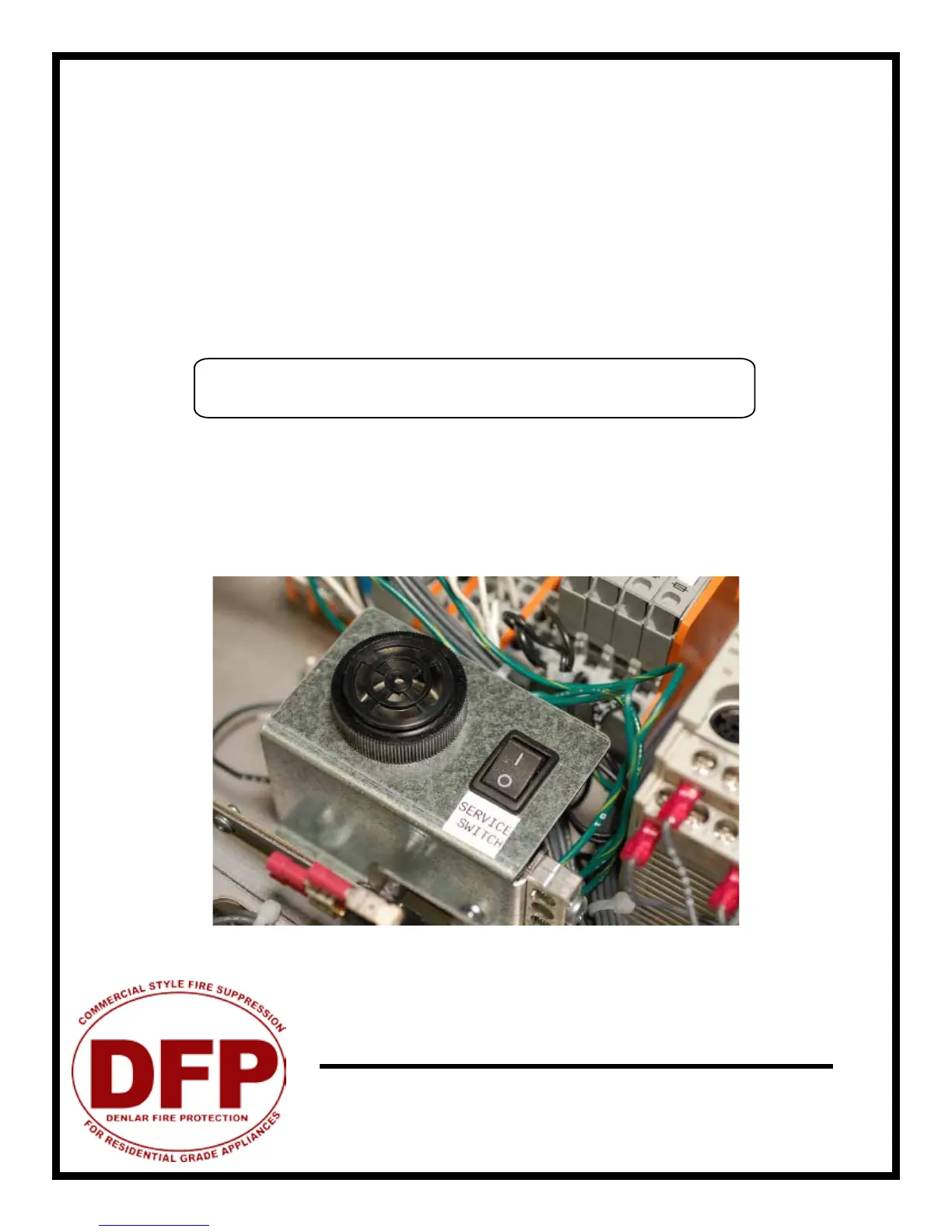
Service Switch: The black switch next to the PLC and internal audible alarm is the service switch. It can be
switched
on or oFF. When it is switched to on, the remote alarm and local alarm are deactivated. Its purpose is to
allow service to be conducted and components tested without setting o the alarm. Once testing or service is
done, turn the service switch to oFF for normal operation. *NOTE: LED will ash orange and green.
Service switch in oFF position
PLC Schematic - Alarm Connections