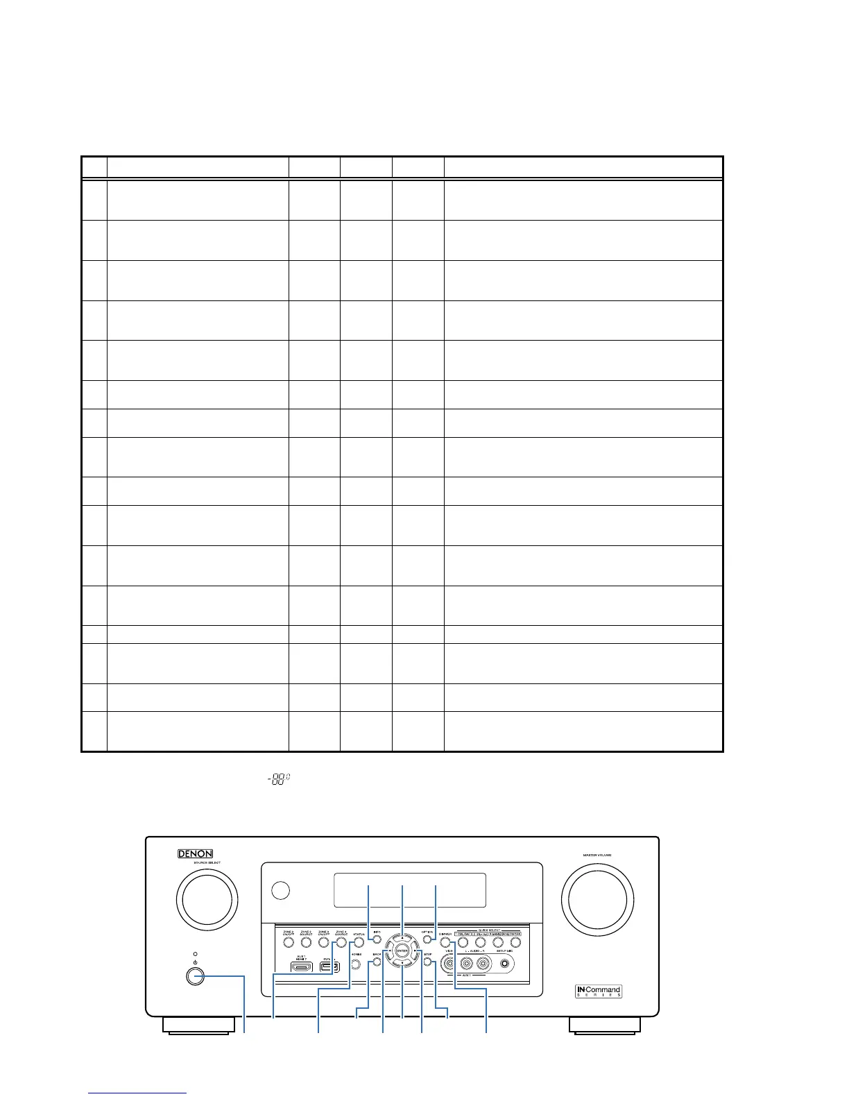
SPECIAL MODE
Special Mode Conguration Buttons
b
No. 1 - 12, 15 : Hold down buttons"
A
", "
B
" and "
C
" at the same time and press the power button to turn on the power.
b
No. 13, 14 : Hold down buttons "
A
" and "
B
" for at least 3 seconds while the power is on.
b
No. 16 : Press the "
A
" and "
B
"
buttons simultaneously while inserting the AC plug to turn the power on.
1
Version Display
(u-COM / DSP Error Display)
SETUP OPTION -
Displays the version of rmware such as the main rmware or DSP,
etc. Errors that have occurred are displayed.
(See 19 page)
2
User Initialization Mode
(Settings for the Installer Setup are not
initialized.)
BACK INFO -
Initializes backup data.
(Settings for the Installer Setup are not initialized.)
3
Factory Initialization Mode
(Initialization includes settings for the
Installer Setup.)
CURSOR
d
CURSOR
f
-
Initializes backup data.
(Initialization includes settings for the Installer Setup.)
4
PANEL / REMOTE LOCK Selection Mode STATUS INFO -
Start this unit in the PANEL/REMOTE LOCK selection mode so that
PANEL LOCK and Remote Lock can be selected as ON or OFF.
(See 23 page)
5
Check the Video/Audio pass
Mode
STATUS
ZONE3
SOURCE
-
This is a special mode for service conrmation used during repair
work to simplify the conrmation work for the Audio channel/vid-
eo channel. (See 27 page)
6
Protection History Display Mode ↑ ↑ -
Displays the protection occurrence history.
(See 71 page)
7
232C Standby Clear Mode : ↑ ↑ -
Switches from 232C standby mode to normal standby mode.
(See 72 page)
8
Operation Info Mode ↑ ↑ -
Displays the total operating time of the set, number of times the
power was switched on, and number of occurrences of each pro-
tection.(See 73 page)
9
TUNER STEP mode
(E3 and E2 model only)
↑ ↑ -
Enables reception STEP of the ANALOG TUNER to be changed.
(See 74 page)
10
Remote ID Setup Mode ↑ ↑ -
If there are multiple DENON AV receivers in the same area, this
mode stops the other AV receivers from being operated concur-
rently with this device. (See 75 page)
11
Installer Setup Mode
CURSOR
0
BACK -
Access the Remote Maintenance mode via the internet. Installer
Setup is displayed on Setup menu / Network.
b
Refer to AVR_RemoteMaintenance_.pdf of SDI.
12
Protection Pass Mode
CURSOR
0
STATUS
ZONE3
SOURCE
Enables the power to be turned on when protection detection is in
the stopped state.
(See 76 page)
13
CX870 / CY920 Reboot mode DIMMER SETUP - CX870 / CY920 をリセット (See76 page)
14
CX870 / CY920 Initialization mode DIMMER
CURSOR
1
-
Enter this mode only after replacing Flash for CX870 / CY920 and
rewriting the rmware.
(See 77 page)
15
USB Update Mode STATUS OPTION
Switches this unit to USB Update mode.
(See 81 page)
16
Forced USB All Device Write Mode STATUS OPTION -
Mode used when this unit cannot be recovered.
Forcibly switches this unit to USB update mode.
(See 83 page)
When the volume indicator displays " ", the set has entered a special mode for developers.
In this case, RS-232C communication cannot be used.
To cancel this special mode, press and hold the "
CURSOR
f
"and "
STATUS
" buttons for 3 seconds and longer. When the volume indica-
tor returns to the normal display, RS-232C communication can be used.
X
ZONE3
SOURCE
d
0 1
STATUS DIMMER
INFO OPTION
SETUPBACK
f
18

 Loading...