Pin Pin Name Symbol I/O Pu/Pd STBY STOP
CEC
STBY
Function
143 PD7/IRQ7/AN107 DIR_CE O L L L DIR (PCM9211) control pin
144 PG1 DIR_DOUT I
DA3.3Pu
I I I DIR (PCM9211) control pin
145 PD6/IRQ6/AN106 DIR_CLK O L L L DIR (PCM9211) control pin
146 PG0 DIR_RST O L L L DIR (PCM9211) control pin
147 PD5/IRQ5/AN113 787_HAINT I - Z - HDMI Rx (MN864787) audio interrupt signal det
148 PD4/IRQ4/AN112 DSP4CS O - Pd Z L DSP(ADI) control pin
149 P97 DE_RST O Pd Z L Video decoder (ADV7850) reset control pin
150 PD3/IRQ3/AN111 787_HINT I - Z - HDMI Tx (MN864787) interrupt signal input pin
151 VSS VSS - - - - Ground pin
152 P96 787_RST O Pd Z ※ HDMI Tx (MN864787) reset control pin
153 VCC VCC - - - - Power supply pin
154 PD2/IRQ2/AN110 788_2_HINT I - Z - HDMI Rx (MN864788) interrupt signal input pin
155 P95 788_2_RST O Pd Z ※ HDMI Rx (MN864788) reset control pin
156 PD1/IRQ1/AN109 788_1_HINT I - Z - HDMI Rx (MN864788) interrupt signal input pin
157 P94 788_1_RST O Pd Z ※ HDMI Rx (MN864788) reset control pin
158 PD0/IRQ0/AN108 ARC_RST O L L L Reset control pin for ARC IC
159 P93/AN117
THERMAL_A
I
SW3VPu
I L I Protection detect signal input pin (for power TR)
160 P92/RXD7/AN116 DA_POWER1 O L L L Digital audio power supply (DA3.3V,DA1.2V) control pin
161 P91/AN115
THERMAL_E
(X6400H), FANDET_
HIGH (SR8012)
I/I
SW3VPu
I/I L I/I
Protection detect signal input pin (for Heat sink)(X6400H),
Thermally detection input pin (for FAN control)(SR8012)
162 VSS VSS - - - - Ground pin
163 P90/TXD7/AN114
THERMAL_F
I/I
SW3VPu
I/I L I/I Protection detect signal input pin (for Heat sink)
164 VCC VCC - - - - Power supply pin
165
P47/IRQ15-DS/
AN007
ARC_INT I L L L ARC IC interrupt signal input pin
166
P46/IRQ14-DS/
AN006
CURRENT_DET
I/O I/L L/L I/L Current level monitor pin (A/D converter)
167
P45/IRQ13-DS/
AN005
AMPSIGDET
I I L I Signal level monitor pin (AD converter)
168
P44/IRQ12-DS/
AN004
MODE I I I I Region setting pin
169
P43/IRQ11-DS/
AN003
KEY3 I
M3VPu
I I I
Key control signalinput pin (When standby mode,set to
inturrupt)
170
P42/IRQ10-DS/
AN002
KEY2 I
M3VPu
I I I
Key control signalinput pin (When standby mode,set to
inturrupt)
171
P41/IRQ9-DS/
AN001
KEY1 I
M3VPu
I I I
Key control signalinput pin (When standby mode,set to
inturrupt)
172 VREFL0 VREFL0 - - - - Ground pin
173 P40 SEL_CLK O L L L Audio selector control pin (NJU72750/72751)
174 VREFH0 VREFH0 - - - - Power supply pin
175 AVCC0 AVCC0 - - - - Power supply pin
176 P07/IRQ15
DSP2FLAG3
I
Pd
L L L DSP(ADI) control pin
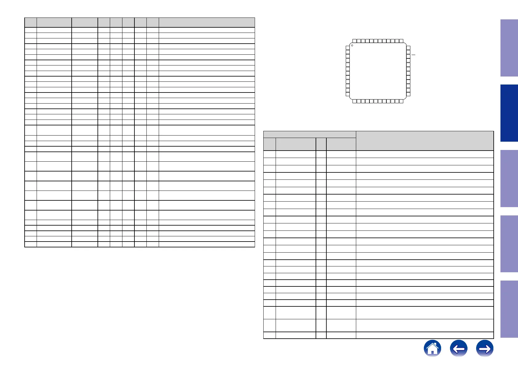
PCM9211 (DIGITAL : U7004)
PIN Functions
PIN
DESCRIPTION
NO. NAME I/O
5-V
TOLERANT
1 ERROR/INT0 O No DIR Error detection output / Interrupt0 output
2 NPCM/INT1 O No DIR Non-PCM detection output / Interrupt1 output
3 MPIO_A0 I/O Yes Multipurpose I/O, Group A(1)
4 MPIO_A1 I/O Yes Multipurpose I/O, Group A(1)
5 MPIO_A2 I/O Yes Multipurpose I/O, Group A(1)
6 MPIO_A3 I/O Yes Multipurpose I/O, Group A(1)
7 MPIO_C0 I/O Yes Multipurpose I/O, Group C(1)
8 MPIO_C1 I/O Yes Multipurpose I/O, Group C(1)
9 MPIO_C2 I/O Yes Multipurpose I/O, Group C(1)
10 MPIO_C3 I/O Yes Multipurpose I/O, Group C(1)
11 MPIO_B0 I/O Yes Multipurpose I/O, Group B(1)
12 MPIO_B1 I/O Yes Multipurpose I/O, Group B(1)
13 MPIO_B2 I/O Yes Multipurpose I/O, Group B(1)
14 MPIO_B3 I/O Yes Multipurpose I/O, Group B(1)
15 MPO0 O No Multipurpose output 0
16 MPO1 O No Multipurpose output 1
17 DOUT O No Main output port, serial digital audio data output
18 LRCK O No Main output port, LR clock output
19 BCK O No Main output port, Bit clock output
20 SCKO O No Main output port, System clock output
21 DGND – – Ground, for digital
22 DVDD – – Power supply, 3.3 V (typ.), for digital
23 MDO/ADR0 I/O Yes Software control I/F, SPI data output / I2C slave address
setting0(2)
24 MDI/SDA I/O Yes Software control I/F, SPI data input / I2C data input/output(2)
(3)
25 MC/SCL I Ye s Software control I/F, SPI clock input / I2C clock input(2)
36
35
34
33
32
31
30
29
28
27
26
25
1
2
3
4
5
6
7
8
9
10
11
12
ERROR/INT0
NPCM/INT1
MPIO_A0
MPIO_A1
MPIO_A2
MPIO_A3
MPIO_C0
MPIO_C1
MPIO_C2
MPIO_C3
MPIO_B0
MPIO_B1
VDDRX
RXIN1
RST
RXIN2
RXIN3
RXIN4/ASCKIO
RXIN5/ABCKIO
RXIN6/ALRCKIO
RXIN7/ADIN0
MODE
MS/ADR1
MC/SCL
48 47 46
45
44 43
42
41
40 39 38
13
14
15 16
17
18 19 20
21 22
23
37
24
PCM9211
VINR
VINL
VCCAD
AGNDAD
VCOM
FILT
VCC
AGND
XTO
XTI
GNDRX
RXIN0
MPIO_B2
MPIO_B3
MPO0
MPO1
DOUT
LRCK
BCK
SCKO
DGND
DVDD
MDI/SDA
PCM9211
www.ti.com
SBAS495 –JUNE 2010
PIN CONFIGURATIONS
PT PACKAGE
LQFP-48
(TOP VIEW)
PIN FUNCTIONS
PIN
5-V
NO. NAME I/O TOLERANT DESCRIPTION
1 ERROR/INT0 O No DIR Error detection output / Interrupt0 output
2 NPCM/INT1 O No DIR Non-PCM detection output / Interrupt1 output
3 MPIO_A0 I/O Yes Multipurpose I/O, Group A
(1)
4 MPIO_A1 I/O Yes Multipurpose I/O, Group A
(1)
5 MPIO_A2 I/O Yes Multipurpose I/O, Group A
(1)
6 MPIO_A3 I/O Yes Multipurpose I/O, Group A
(1)
7 MPIO_C0 I/O Yes Multipurpose I/O, Group C
(1)
8 MPIO_C1 I/O Yes Multipurpose I/O, Group C
(1)
9 MPIO_C2 I/O Yes Multipurpose I/O, Group C
(1)
10 MPIO_C3 I/O Yes Multipurpose I/O, Group C
(1)
11 MPIO_B0 I/O Yes Multipurpose I/O, Group B
(1)
12 MPIO_B1 I/O Yes Multipurpose I/O, Group B
(1)
13 MPIO_B2 I/O Yes Multipurpose I/O, Group B
(1)
14 MPIO_B3 I/O Yes Multipurpose I/O, Group B
(1)
15 MPO0 O No Multipurpose output 0
(1) Schmitt trigger input
Copyright © 2010, Texas Instruments Incorporated Submit Documentation Feedback 7
Product Folder Link(s): PCM9211
61
Caution in
servicing
Electrical Mechanical Repair Information Updating
 Loading...