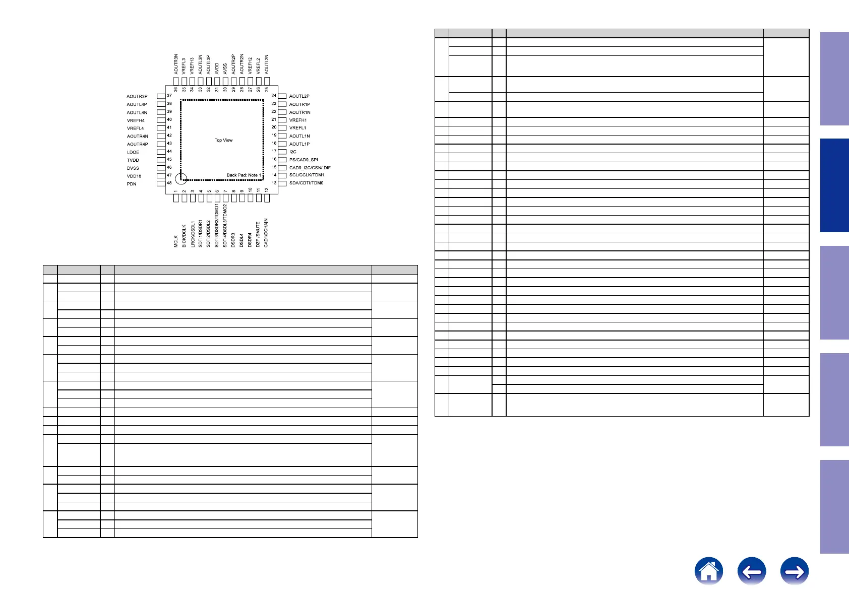
AK4458VN (DAC : U7501, U7502)
Pin Function
No. Pin Name I/O Function PD State
1 MCLK I External Master Clock Input Pin Hi-Z
2
BICK I Audio Serial Data Clock Pin in PCM mode
Hi-z
DCLK I DSD Clock Pin in DSD mode
3
LRCK I Input Channel Clock Pin in PCM mode
Hi-Z
DSDL1 I Audio Serial Data Input in DSD mode
4
SDTI1 I Audio Serial Data Input in PCM mode
Hi-Z
DSDR1 I Audio Serial Data Input in DSD mode
5
SDTI2 I Audio Serial Data Input in PCM mode
Hi-Z
DSDL2 I Audio Serial Data Input in DSD mode
6
SDTI3 I Audio Serial Data Input in PCM mode
100k Ω
Pull down
DSDR2 I Audio Serial Data Input in DSD mode
TDMO1 O Audio Serial Data Output in Daisy Chain mode
7
SDTI4 I Audio Serial Data Input in PCM mode
100k Ω
Pull down
DSDL3 I Audio Serial Data Input in DSD mode
TDMO2 O Audio Serial Data Output in Daisy Chain mode
8 DSDR3 I Audio Serial Data Input in DSD mode Hi-Z
9 DSDL4 I Audio Serial Data Input in DSD mode Hi-Z
10 DSDR4 I Audio Serial Data Input in DSD mode Hi-Z
11
DZF O Zero Input Detect in I2C Bus or 3-wire serial control mode
100k Ω
Pull down
SMUTE I
Soft Mute Pin in Parallel control mode.
When this pin is changed to "H", soft mute cycle is initiated. When it is returning to "L", the
output mute is released.
12
CAD1 I Chip Address 0 Pin in I C Bus or 3-wire serial control mode
Hi-Z
DCHAIN I Daisy Chain Mode select pin in Parallel control mode.
13
SDA I/O Control Data Pin in I2C Bus serial control mode
Hi-ZCDTI I Control Data Input Pin in 3-wire serial control mode
TDM0 I TDM Mode select pin in Parallel control mode.
14
SCL I Control Data Clock Pin in I2C Bus serial control mode
Hi-ZCCLK I Control Data Clock Pin in 3-wire serial control mode
TDM1 I TDM Mode select pin in Parallel control mode.
[AK4458]
014011794-E-00 2015/01
- 7 -
5. Pin Configurations and Functions
Ordering Guide
AK4458VN 40
+105 C (Exposed pad is connected to ground)
40 +85 C (Exposed pad is open)
48-pin QFN (0.5mm pitch)
AKD4458 Evaluation Board for AK4458
Pin Configurations
Note 1. The exposed pad at back face of the package must be open or connected to the ground of the board.
No. Pin Name I/O Function PD State
15
CAD0_I2C I Chip Address 0 Pin in I2C Bus serial control mode
Hi-Z
CSN I Chip Select Pin in 3-wire serial control mode
DIF I Audio Data Format Select in Parallel control mode. "L": 32-bit MSB, "H": 32-bit I2S
16
PS I
(I2C pin = "H") Control Mode Select Pin "L": I2C Bus serial control mode, "H": Parallel control
mode.
Hi-Z
CAD0_SPI I (I2C pin = "L") Chip Address 0 Pin in 3-wire serial control mode
17 I2C I
Control Mode Select Pin "L": 3-wire serial control mode
"H": I2C Bus serial control mode or Parallel control mode.
Hi-Z
18 AOUTL1P O Lch Positive Analog Output 1 Pin Hi-Z
19 AOUTL1N O Lch Negative Analog Output 1 Pin Hi-Z
20 VREFL1 I Negative Voltage Reference Input Pin, AVSS Hi-Z
21 VREFH1 I Positive Voltage Reference Input Pin, AVDD Hi-Z
22 AOUTR1N O Rch Negative Analog Output 1 Pin Hi-Z
23 AOUTR1P O Rch Positive Analog Output 1 Pin Hi-Z
24 AOUTL2P O Lch Positive Analog Output 2 Pin Hi-Z
25 AOUTL2N O Lch Negative Analog Output 2 Pin Hi-Z
26 VREFL2 I Negative Voltage Reference Input Pin, AVSS Hi-Z
27 VREFH2 I Positive Voltage Reference Input Pin, AVDD Hi-Z
28 AOUTR2N O Rch Negative Analog Output 2 Pin Hi-Z
29 AOUTR2P O Rch Positive Analog Output 2 Pin Hi-Z
30 AVSS - Analog Ground Pin -
31 AVDD - Analog Power Supply Pin, 3.0V-5.5V -
32 AOUTL3P O Lch Positive Analog Output 3 Pin Hi-Z
33 AOUTL3N O Lch Negative Analog Output 3 Pin Hi-Z
34 VREFH3 I Positive Voltage Reference Input Pin, AVDD Hi-Z
35 VREFL3 I Negative Voltage Reference Input Pin, AVSS Hi-Z
36 AOUTR3N O Rch Negative Analog Output 3 Pin Hi-Z
37 AOUTR3P O Rch Positive Analog Output 3Pin Hi-Z
38 AOUTL4P O Lch Positive Analog Output 4 Pin Hi-Z
39 AOUTL4N O Lch Negative Analog Output 4 Pin Hi-Z
40 VREFH4 I Positive Voltage Reference Input Pin, AVDD Hi-Z
41 VREFL4 I Negative Voltage Reference Input Pin, AVSS Hi-Z
42 AOUTR4N O Rch Negative Analog Output 4 Pin Hi-Z
43 AOUTR4P O Rch Positive Analog Output 4 Pin Hi-Z
44 LDOE I Internal LDO Enable Pin. "L": Disable, "H": Enable Hi-Z
45 TVDD - Digital Power Supply Pin, 3.0V-3.6V -
46 DVSS - Digital Ground Pin -
47 VDD18
O LDO Output Pin (LDOE pin = "H") This pin should be connected to DVSS with 1.0µF.
(Note 4)
I 1.8V Power Input Pin (LDOE pin = "L")
48 PDN I
Power-Down & Reset Pin
When this pin is "L", the AK4458 is powered-down and the control registers are reset to default
state.
Hi-Z
Note 2. All input pins except internal pull-up/down pins should not be left oating.
Note 3. PCM mode and DSD mode are controlled by registers. Daisy Chain mode is controlled by both
registers and pins.
Note 4. This pin outputs DVSS when the LDOE pin = "H" and Hi-z when the LDOE pin = "L".
64
Caution in
servicing
Electrical Mechanical Repair Information Updating
 Loading...