26
DHT-FS5
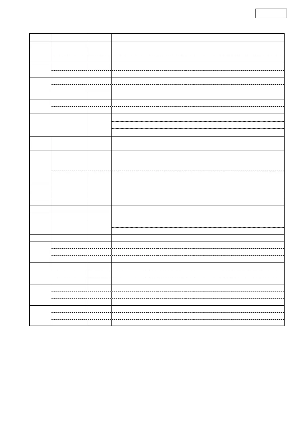
No. Pin Name I/O Function
11 RX1 I Receiver Channel #1 Pin (Internal Biased Pin)
DIF0 I Audio Data Interface Format #0 Pin in parallel control mode
12
RX2 I Receiver Channel #2 Pin in serial control mode (Internal Biased Pin)
DIF1 I Audio Data Interface Format #1 Pin in parallel control mode
13
RX3 I Receiver Channel #3 Pin in serial control mode (Internal Biased Pin)
DIF2 I Audio Data Interface Format #2 Pin in parallel control mode
14
RX4 I Receiver Channel #4 Pin in serial control mode (Internal Biased Pin)
15 RX5 I Receiver Channel #5 Pin (Internal Biased Pin)
IPS I Input Channel Select Pin in parallel control mode
16
RX6 I Receiver Channel #6 Pin (Internal Biased Pin)
Interrupt #1 Pin (when BCU bit = “0”)
U-bit Output Pin (when BCU bit = “1”, UCE bit = “0”)
17 INT1 O
C-bit Output Pin (when BCU bit = “1”, UCE bit = “1”)
18
P/SN
I
Parallel/Serial Select Pin
“L”: Serial control mode, “H”: Parallel control mode
FS96 O
96kHz Sampling Detect Pin in parallel control mode
This function is enabled when the input frequency of XTI is 24.576MHz.
“L”: fs=54kHz or less, “H”: fs=64kHz or more
19
I2C I
I
2
C Select Pin in Serial control mode.
“L”: 4-wire Serial, “H”: I
2
C
20 INT0 I Interrupt #0 Pin
21 LRCK I/O Output Channel Clock Pin
22 SDTO O Audio Serial Data Output Pin
23 BICK I/O Audio Serial Data Clock Pin
24 DAUX I Auxiliary Audio Data Input Pin
Master Clock #2 Output Pin (when BCU bit = “0”)
25 MCKO2 O
Block Start Signal Output Pin (when BCU bit = “1”)
26 MCKO1 O Master Clock #1 Output Pin
OCKS0 I Output Clock Select #0 Pin in parallel control mode
CSN I Chip Select Pin in serial control mode, I2C pin = “L”
27
CAD0 I Chip Address #0 Pin in serial control mode, I2C pin = “H”
OCKS1 I Output Clock Select #1 Pin in parallel control mode
CCLK I Control Data Clock Pin in serial control mode, I2C pin = “L”
28
SCL I Control Data Clock Pin in serial control mode, I2C pin = “H”
CM1 I Master Clock Operation Mode #1 Pin in parallel control mode
CDTI I Control Data Input Pin in serial control mode, I2C pin = “L”
29
SDA I/O
Control Data Pin in serial control mode, I2C pin = “H”
CM0 I Master Clock Operation Mode #0 Pin in parallel control mode
CDTO O Control Data Output Pin in serial control mode
30
CAD1 I Chip Address #1 Pin in serial control mode, I2C pin = “H”
Note 1. Do not allow digital input pins expect internal biased pins (RX1-6 pins) to float.

 Loading...