28
Before use Connections
Basic
operations
Installing and setting up
supplied software
USB settings
Troubleshooting Index
Specifications
Signal system chart
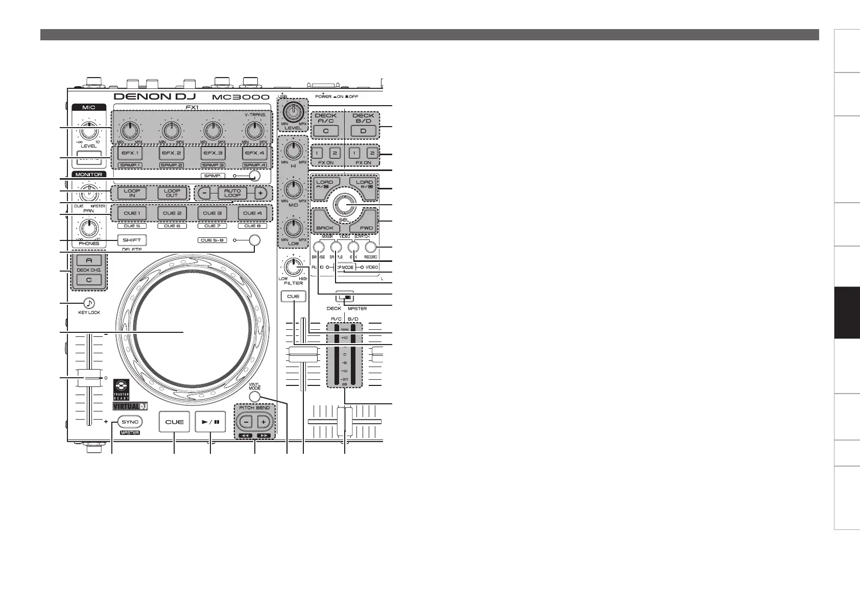
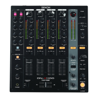
Part names and
functions
E0 SAMPLE window switch button
(SAMPLE)
Hold down u SHIFT and press this button for
more than 1 second to assign each DECK to the
following MIDI channels.
•DECK A ............MIDI CHANNEL 5
•DECK B ............MIDI CHANNEL 7
•DECK C ............MIDI CHANNEL 6
•DECK D ............MIDI CHANNEL 8
E1 BROWSE window switch button
(BROWSE)
Hold down u SHIFT and press this button for
more than 1 second to assign each DECK to the
following MIDI channels.
•DECK A ............MIDI CHANNEL 1
•DECK B ............MIDI CHANNEL 3
•DECK C ............MIDI CHANNEL 2
•DECK D ............MIDI CHANNEL 4
E2 Level meter display switching switch
(DECK, MASTER)
Channels displayed by the level master can be
selected from the following display modes.
DECK:
DECKA/Clevelisdisplayedintheleftchannel,
and DECK B/D level is displayed in the right
channel.
MASTER:
The volume level of the master output volume
(L/R)isdisplayed.
E3 Filter cut off adjustment knob (FILTER)
Adjusts the filter cut off frequency for each
channel.
E4 Channel cue button (CUE DECK A/B/C/D)
The source of the channel selected using y
CUE is mixed with the monitor.
E5 Channel/master level meter
Displays the volume level of the channel
selected with the E2 level meter display
switching switch.
Q3 Q6 Q9Q4 Q5 Q7
E5
E1
E4
E2
W9
E3
E0
Q8
W7
W5
W6
W4
W0
W1
W2
W3
W8
q
w
r
t
i
o
Q0
Q2
Q1
y
u
e
Top panel