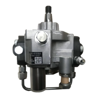
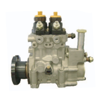
8
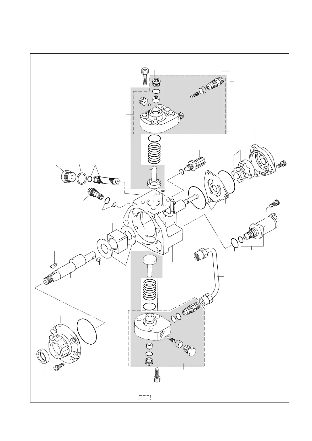
2. Disassembly Chart
This disassembly chart uses pump No. 294000-001# as a reference. When working on another
model, please refer to the parts list.
Element Assembly
Filter
Plug
Gasket
Filter Sub-
Assembly
Plunger
Regulating
Valve
O-Rings
Drive Shaft Key
Key
Washers
Ring Cam
Pump Body
Drive Shaft
Oil Seal
Cover Sub-
Assembly
O-Ring
Pipe
O-Ring
SCV
Pins
Plate, Feed Pump
O-Ring
O-Ring
O-Ring
O-Ring
Spring
Rotor
Set
Feed Pump Cover
Temperature
Sensor
O-Ring
QD1850E
NOTE:
Do not disassemble this portion.
NOTE:
To replace any part in this area, the entire
assembly in the shaded area must be replaced.
NOTE:
Do not disassemble the parts in the area marked [ ] because they need to be angle-tightened for reassembly.
NOTE:
To replace any part in this area, the entire
assembly in the shaded area must be replaced.
NOTE:
Do not disassemble this portion.