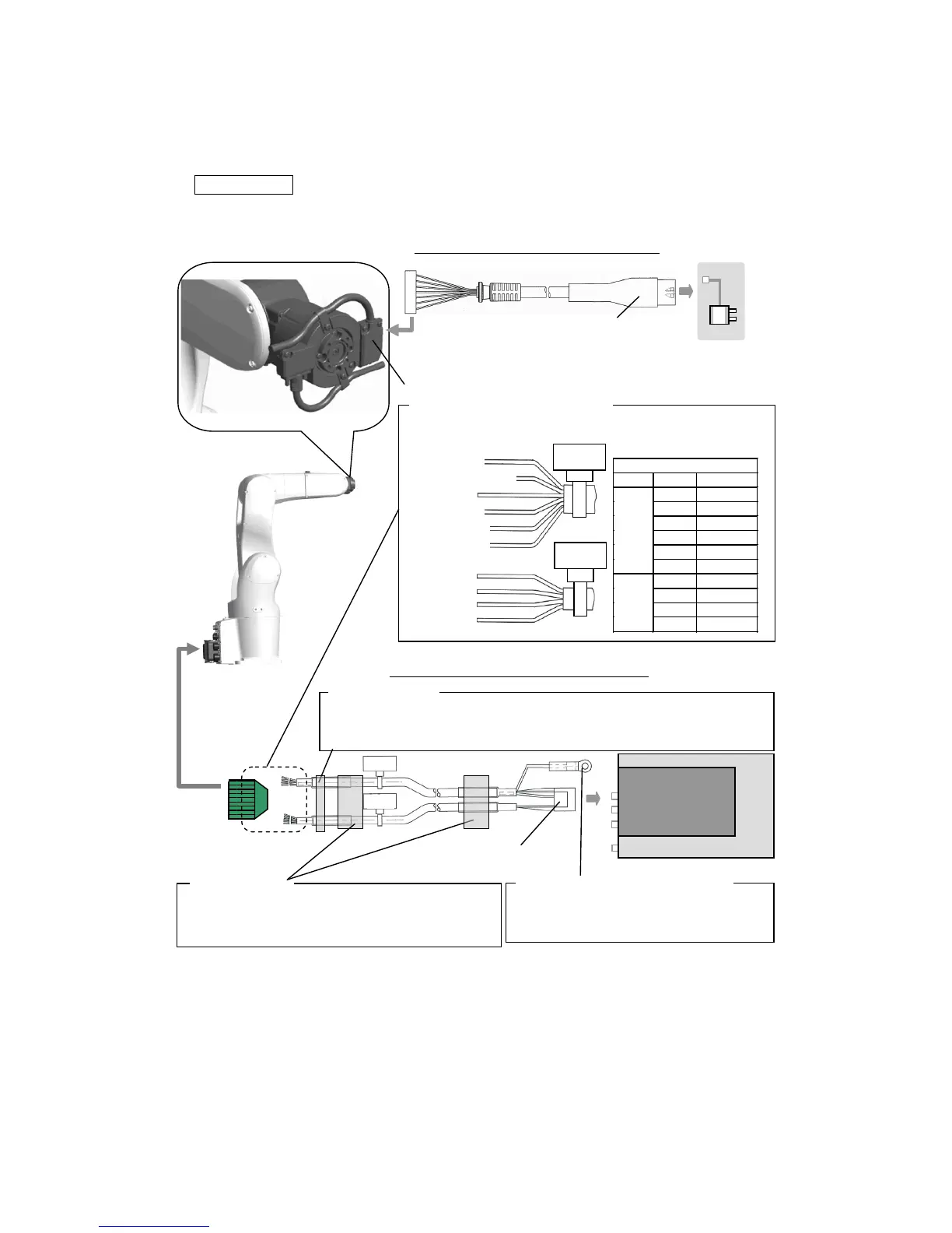
Connect as shown in the diagram below.
Electric gripper
control board
If the noise environment is poor or if CE conformity is
required, attach the ferrite core (large) provided near the
control board. Refer to “Prevention of Malfunction by Noise”
for details.
If the noise environment is poor or if CE conformity is required, attach the ferrite core
(small) provided near the CN20 connector. Refer to “Prevention of Malfunction by
Noise” for details.
Connection wires prepared by customer
Refer to the guidelines of each robot for details on how to connect
wires to connectors. The pin arrangement is shown in the table
below.
Signal wiring connector (inside cover)
To signal wiring connector
(Open cover and
connect.)
Electric gripper connection cable (C connection)
Electric gripper
connector
Electric gripper connection cable (B, C connection)
Electric gripper connection cable FG wire
Secure the FG wire to the robot controller front
panel with a screw. Refer to “Electric gripper
connection cable FG connection” for details