Model FP-700
FP-700 Instruction Manual Rev. 5.1 Page 8 of 46
2.4 Mounting Installation
The FP-700 sensor assembly is designed to be threaded into a ¾” Female NPT fitting of a standard cast metal,
Explosion-Proof Enclosure or Junction Box. Thread the sensor up until tight (5 turns is typically expected) and
until the display is pointed in the direction that sensor will normally be viewed and accessed.
The FP-700 should be vertically oriented so that the sensor points straight downward. The explosion-proof
enclosure or junction box would then typically be mounted on a wall or pole. Detcon provides a standard
selection of junction boxes available as sensor accessories (See Figures 9, 10, 11, and 12 below), but any
appropriately rated enclosure with a downward facing ¾” NPT female connection will suffice.
When mounting on a wall, it is recommended to use a 0.25”-0.5” spacer underneath the mounting ears of the
Detcon standard J-Box to offset the sensor assembly from the wall and create open access around the sensor
assembly. Spacing requirements for other junction boxes may vary.
When mounting on a pole, secure the Junction Box to a suitable mounting plate and attach the mounting plate
to the pole using U-Bolts. (Pole-Mounting brackets for Detcon J-box accessories are available separately.)
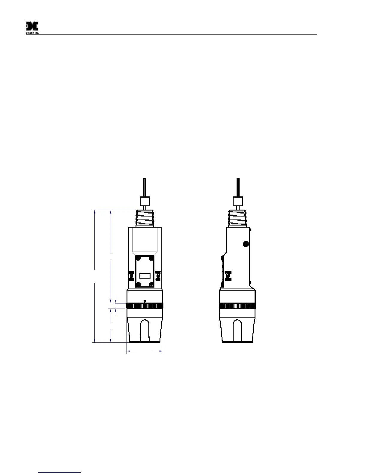
Male 3/4" NPT Threads
Sensor Assembly
Splash Guard
2.125"
7.8"
Typ.
Ferrite Cylinder
Sensor Wires
2"
0.3"
5.48"
detcon inc.
LEL Sensor
MODEL
FP-700
Figure 9 Outline and Mounting Dimensions (Sensor Assembly only)