Model FP-700
FP-700 Instruction Manual Rev. 5.1 Page 17 of 46
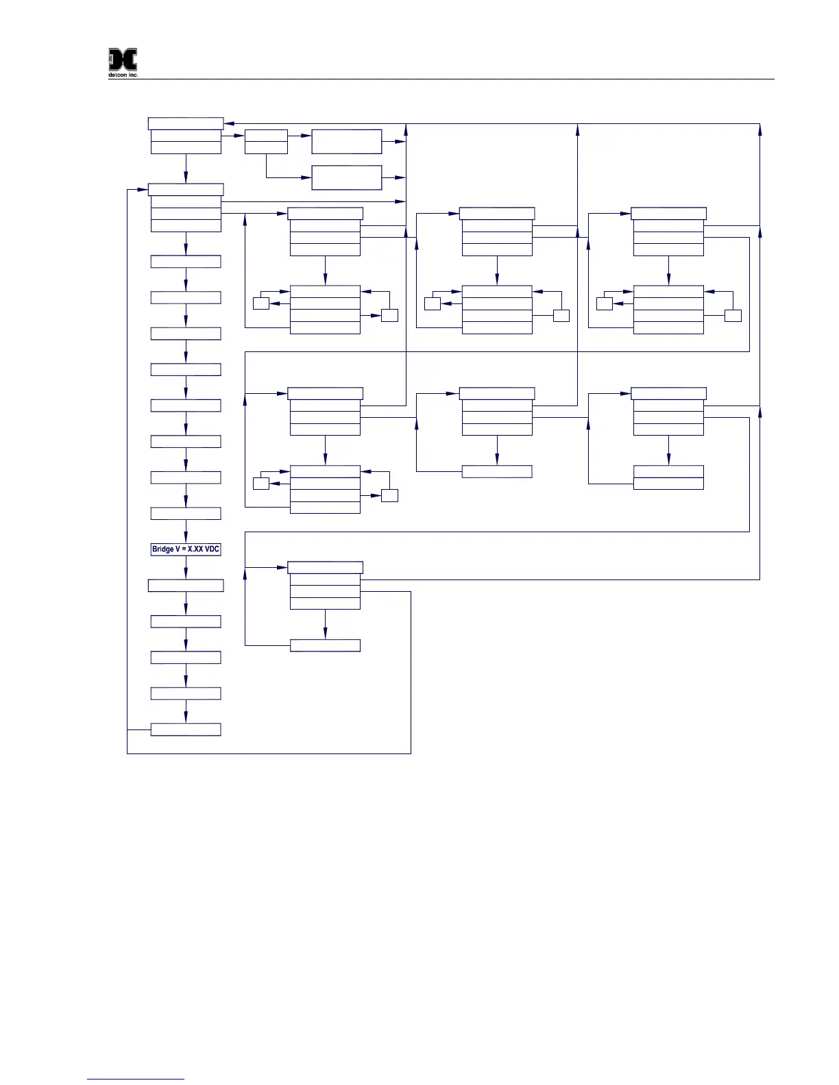
Software Flowchart
dec
Temp = XX C
mA Output = X.XX
Cal Factor = X.XX
Voltage = X.XX V
Sensor Life XXX%
Gas Factor = X.XX
Bridge A = XXX mA
PGM2 (10)
Defaults Restored
Restore Defaults
Auto Time-Out
PGM1/2 (M)
Setting Bridge
Calibration Mode
(Auto Span)
AutoSpan @ XX
Last Cal XX Days
Serial ID XX
Range XXX
Auto Time-Out
Version X.XX
View Sensor Status
Model Type
PGM1/2 (3)
PGM1/2 (M)
inc
PGM1 (S)
Set Serial ID
PGM1/2 (3)
PGM1/2 (M)
PGM1/2 (3)
Auto Time-Out
AutoTime-out
XX
PGM2 (S)
PGM1/2 (3)
PGM1/2 (M)
Set AutoSpan Level
PGM1 (3)
PGM2 (3)
Normal Operation
PGM1 (3)
PGM2 (10)
Calibration Mode
(Auto Zero)
inc - Increase
dec - Decrease
X, XX, XXX - numeric values
(S) - Momentary Swipe
(M) - Momentary hold of Magnet during teXt
scroll until the ">" appears, then release
(3) - 3 second hold from ">" prompt
(10) - 10 second hold from ">" prompt
Auto Time-out - 5 seconds
PGM1 - Program Switch Location X1
PGM2 - Program Switch Location X2
LEGEND:
inc
PGM2 (S)
PGM1/2 (3)
PGM1 (S)
XX
dec
PGM1/2 (3)
Simulation
Auto Time-Out
Set Cal Factor
Auto Time-Out
Signal Output Check
Auto Time-Out
Set Bridge Voltage
Auto Time-Out
Set Gas Factor
PGM1 (S)
PGM1/2 (3)
PGM1/2 (M)
PGM1/2 (3)
inc
PGM1/2 (3)
PGM2 (S)
XX
PGM1/2 (M)
dec
inc
dec
PGM1 (S)
PGM2 (10)
PGM1/2 (M)
PGM1/2 (3)
PGM1/2 (3)
PGM2 (S)
XX
PGM1/2 (M)
Figure 17 FP-700 Software Flowchart
3.3 Normal Operation
In normal operation, the ITM Display continuously shows the current sensor reading, which will normally appear
as “ 0 ”. Once every 60 seconds the LED display will flash the sensor’s measurement units and gas type (i.e. %
LEL). If the sensor is actively experiencing any diagnostic faults, a “Fault Detected” message will flash on the
ITM display every 60 seconds. At any time, while the unit is in “Fault Detected” mode, PGM1 or PGM2 can
be swiped to prompt the sensor to display the list of the active faults.
In normal operation, the 4-20mA current output corresponds with the present gas concentration and full-scale
range. The RS-485 Modbus™ serial output provides the current gas reading and fault status on a continuous
basis when polled.