Model FP-700
FP-700 Instruction Manual Rev. 5.1 Page 12 of 46
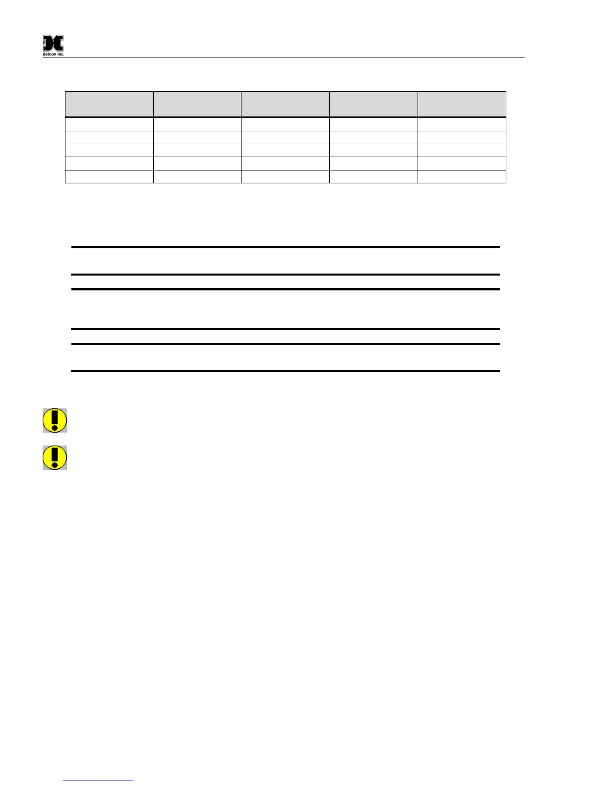
Table 1 Wire Gauge vs. Distance
AWG Wire Dia. Meters Feet
Max loop load resistance between green and black wire is 500 ohms. Minimum loop load resistance between
green and black wire is 100 ohms. This is considers wire diameter, wire length, max operating temperature and
selected termination resistor.
NOTE 1: Wiring table is based on stranded tinned copper wire and is designed to serve as a
reference only.
NOTE 2: Shielded cable is required for installations where cable trays or conduit runs include
high voltage lines or other possible sources of induced interference. Separate conduit runs are
highly recommended in these cases.
NOTE 3: The supply of power should be from an isolated source with over-current protection
as stipulated in table.
Terminal Connections
CAUTION: Do not apply System power to the sensor until all wiring is properly terminated. Refer to
Section 2.7 Initial Start Up
CAUTION: Do not apply power to the sensor assembly in a hazardous area unless the junction box
cover is tight and all electrical seals have been installed